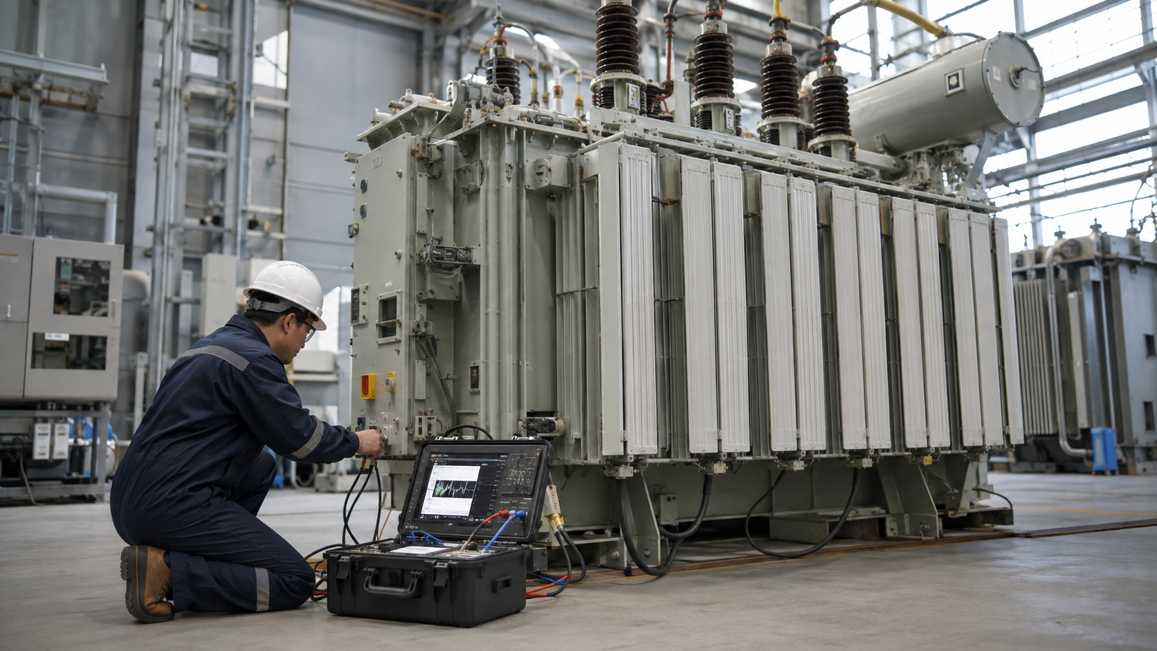
A transformer changes alternating voltage through electromagnetic induction. If a transformer raises the voltage, it will reduce the current for approximately the same transferred apparent power, excluding losses. Three-phase winding connections and vector groups also determine neutral availability, zero-sequence behavior and phase shift. This guide explains step-up/step-down operation, AC versus DC, star and delta connections, vector notation, parallel operation and voltage regulation.
Voltage, Current and Turns Ratio
For an ideal transformer:
V₂ ÷ V₁ = N₂ ÷ N₁
Voltage ratio follows winding turns. Current changes inversely:
I₂ ÷ I₁ = N₁ ÷ N₂
A transformer that steps 400 V up to 10 kV increases voltage by 25 times and ideally reduces current to one twenty-fifth. Real output power is slightly lower because winding, core and stray losses produce heat.
Step-Up vs Step-Down Transformers
A step-up transformer has higher output voltage than input voltage in the stated direction of power flow. It is used at generators and renewable plants to reduce transmission current. A step-down transformer supplies lower-voltage distribution and utilization loads.
Many transformers can transfer power in either direction if construction, taps, protection and system grounding permit. “Primary” and “secondary” often describe intended source and load sides, while HV/LV identifies voltage windings more clearly.
Quick Comparison and Selection Table
Use this table as a quick review of the main engineering and procurement decisions explained in the article.
| Decision area | Practical meaning | What to verify |
|---|---|---|
| Voltage, Current and Turns Ratio | For an ideal transformer: V₂ ÷ V₁ = N₂ ÷ N₁ Voltage ratio follows winding turns. | Current changes inversely: I₂ ÷ I₁ = N₁ ÷ N₂ A transformer that steps 400 V up to 10 kV increases voltage by 25 times and ideally reduces current to one twenty-fifth. |
| Step-Up vs Step-Down Transformers | A step-up transformer has higher output voltage than input voltage in the stated direction of power flow. | It is used at generators and renewable plants to reduce transmission current. |
| Will a Transformer Work With DC Voltage? | A conventional transformer requires changing magnetic flux. | Steady DC does not continuously induce secondary voltage. |
| Single-Phase and Three-Phase Windings | A three-phase transformer may use one three-limb core or a bank of single-phase units. | Each phase winding has two ends that can be interconnected in star (wye), delta or, in specialized designs, zigzag. |
| Star (Wye) Connection | In star, one end of each phase winding joins at a neutral point. | Line voltage equals √3 times phase voltage, while line current equals phase current. |
Will a Transformer Work With DC Voltage?
A conventional transformer requires changing magnetic flux. Steady DC does not continuously induce secondary voltage. Applying DC to a normal transformer can produce very high current limited mainly by winding resistance, causing rapid overheating and damage. DC conversion systems use electronic switching to create alternating or pulsed waveforms before magnetic transformation.
Single-Phase and Three-Phase Windings
A three-phase transformer may use one three-limb core or a bank of single-phase units. Each phase winding has two ends that can be interconnected in star (wye), delta or, in specialized designs, zigzag. The connection changes line/phase relationships and system behavior.
Star (Wye) Connection
In star, one end of each phase winding joins at a neutral point. Line voltage equals √3 times phase voltage, while line current equals phase current. The neutral can be grounded and made available for single-phase loads. Insulation per phase can be lower than line voltage, which is advantageous on high-voltage windings.
Delta Connection
In delta, phase windings form a closed loop. Line voltage equals phase voltage, while line current is √3 times phase current. Delta provides a path for triplen harmonic and zero-sequence circulating currents and blocks zero-sequence current from passing directly to the line terminals.
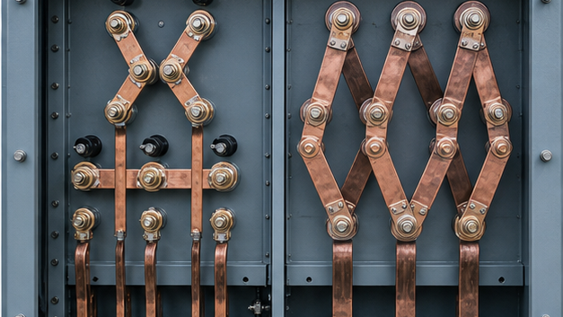
Common Three-Phase Connections
- Yy: star-star; neutrals may be available but zero-sequence and harmonics require careful treatment.
- Dyn: delta HV, star LV with neutral; widely used for distribution.
- Yd: star HV and delta LV; used where a delta secondary suits the system.
- Dd: delta-delta; no neutral and no inherent 30-degree shift.
- Zigzag: useful for grounding, neutral formation and harmonic control.
How Vector Group Notation Works
Letters identify winding connections: D/d for delta, Y/y for star and Z/z for zigzag. Uppercase normally denotes the high-voltage winding and lowercase the lower-voltage winding. “N” or “n” indicates an accessible neutral.
The clock number states LV phase displacement relative to HV in multiples of 30 degrees. Dyn11 therefore describes HV delta, LV star with neutral and an 11-o’clock displacement. The exact reference convention follows the applicable standard.
Why Vector Groups Matter
Vector group affects system phase angle, grounding, earth-fault current, harmonic behavior and parallel compatibility. A wrong replacement transformer can place secondary voltages out of phase, making parallel connection dangerous and disrupting differential protection compensation.
Parallel Transformer Requirements
Before paralleling, verify:
- same voltage ratio and compatible tap position;
- same polarity and phase sequence;
- same vector group or identical phase displacement;
- similar percentage impedance and X/R ratio;
- compatible kVA ratings for proportional load sharing;
- adequate combined fault rating of switchgear and busbars.
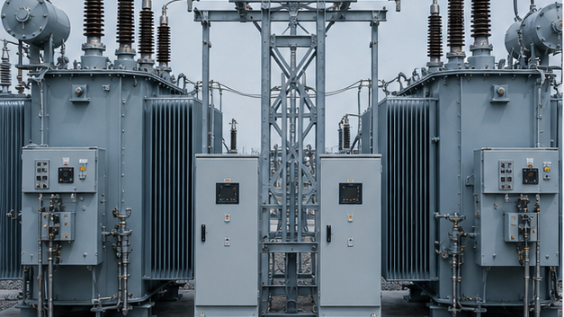
Small ratio differences cause circulating current even without load. Impedance differences cause unequal percentage loading, so one unit may overload before combined nameplate capacity is reached.
Transformer Voltage Regulation
Voltage regulation describes the secondary-voltage change between no-load and load at a stated power factor. Winding resistance and leakage reactance cause internal drop. Load power factor affects both magnitude and direction of change.
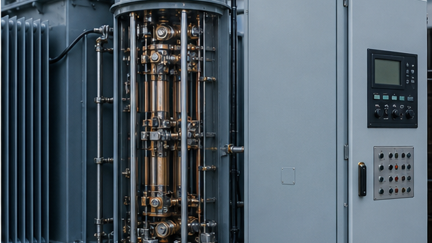
An off-circuit tap changer adjusts ratio only when de-energized. An on-load tap changer (OLTC) changes taps while energized and works with an automatic voltage regulator. The controller uses measured voltage, setpoint, deadband, delay and line-drop compensation to avoid excessive operations.
Protection and Connection Effects
Differential protection must compensate for turns ratio and vector-group phase shift. CT connections or numerical relay settings also prevent zero-sequence current from causing false operation. Neutral grounding and earth-fault protection depend on which neutral is accessible and how it is grounded.
Product Specification
For a 35 kV oil-immersed power transformer, specify HV/LV voltage, vector group, impedance, taps and grounding. Packaged equipment such as the 35 kV new-energy box substation or YBM-12 prefabricated substation must coordinate transformer connection with switchgear protection and LV neutral requirements.
Verification Checklist
- Confirm system voltages and frequency.
- Specify connection and neutral requirements.
- Choose vector group from system and parallel needs.
- Define impedance, taps and regulation.
- Verify zero-sequence and grounding behavior.
- Coordinate differential and earth-fault protection.
- Test ratio, polarity, phase displacement and vector group before energization.
Reading transformer vector-group notation
The first capital letter describes the high-voltage winding, the lowercase letter describes the low-voltage winding, and N or n identifies an accessible neutral. The clock number expresses LV phase displacement relative to HV in 30-degree steps. For example, Dyn11 is delta HV, wye LV with neutral, at clock position 11.
Polarity, phase displacement and paralleling
Polarity establishes instantaneous terminal relationship; phase sequence establishes phase order; vector group establishes winding connection and displacement. Transformers intended for parallel service must provide compatible secondary voltage and phase angle and should have suitably matched impedance and tap positions to avoid circulating current and unequal load sharing.
Technical references and further reading
The following independent sources support the standards, terminology, calculations, and safety context discussed in this guide:
- IEC 60076-1 power transformer standard — Scope, terminology, ratings, connection symbols, testing, safety, and general requirements for power transformers.
- U.S. Department of Energy: Distribution Transformers — Official definitions, efficiency requirements, test procedures, and regulatory resources for distribution transformers.
- OSHA electric power transmission and distribution requirements — Safety requirements relevant to construction and work around electric power transmission and distribution equipment.