With the continuing growth of deep global mining and steel production using electric arc furnaces (EAF), step-down power transformers will be essential for dependable power transmission.
According to the IEA, total investment in power grids globally exceeded USD310 billion in 2023, with upgrade of distribution transformers being the highest priority. Mining and primary metals (both of which are considered among the most ‘heavy duty’ types of electricity users) require extremely stable voltage as verified by current U.S. EIA data. Procurement teams that must evaluate heavy duty power transformers have to consider two things: first, that the standard types of products cannot withstand repeated impact from SAG mill operations and cannot handle the excessive flicker associated with EAF’s, and, second, that most suppliers’ ability to support their claims of having “industrial grade” transformers is not typically supported by independently validated third-party data. Additionally, procuring large quantities of transformers may also expose procurement teams to additional risk by having transformers subjected to conditions such as dust, humidity, and high altitude on-site.
A comprehensive overview of manufacturing a step-up transformer suitable for extreme environments in the mining and steel mill industries. The article goes through the different stages of the transformer engineering process, including load modeling, winding production, enclosure design and testing, and lifetime support.
Modeling Loads and Assessing Engineering – Working with EPC’s to Define the withstand Parameters For EAF Flicker and Crusher Surges
Quantifying true loads is the first step of determining reliability. The importance of early engagement with EPC companies (e.g. Hatch, Bechtel) and the mine owner’s engineers is critical.
Because of the heavy current draw from a SAG mill at start-up (i.e., as much as five to seven times rated current), there is a very deep voltage dip. Also, while operating an AC EAF during scrap melts, short-circuits often occur, and there is frequent voltage flicker (>±20 %), as well as a number of different frequencies that can create harmonics that affect the electrical systems supplying power to both the mining and steel mill in three main ways:
- Sensitive equipment disruption: Voltage fluctuations caused by flicker can disrupt sensitive electronic equipment and variable frequency drives (VFDs) leading to unexpected shutdowns.
- Protection system nuisance tripping: Maloperation of protection relays on adjacent feeders may be caused by repeated voltage fluctuations, which will expand the impact of the disturbance through the factory.
- Grid‑compliance risk: Serious guidelines are set forth for flicker severity limits (Pst, Plt) by IEC 61000‑4‑15 that, if exceeded, could cause failure to obtain approved grid connection for the project.
Correctly defining EAF flicker during initial design phase ensures that no power quality issues will arise post operation. Collecting waveform data at site level and transient simulations provide the baseline specs, including: primary voltage of 13.8 kV or 34.5 kV, secondary voltage options of 480V, 600 V or 690 V, and capacity from 2,500 kVA – 15,000kVA. With impedance levels being much higher (8-12% compared to standard distribution unit of 4-5%) for limiting fault current & stabilizing the electrical arc; see below for how each load type affects design parameters.
| Equipment Type | Load Characteristics | Core Requirement for Step‑Down Transformer |
|---|---|---|
| SAG Mill / Ball Mill | High starting torque, 5–7× inrush | High mechanical strength, vacuum‑impregnated winding |
| Crusher | Cyclic shock loads | Reinforced core clamping, high short‑circuit withstand |
| AC Electric Arc Furnace | Frequent short circuits, ±20 % flicker, high harmonics | 8–12 % impedance, OLTC, Class H insulation |
| Rolling Mill Main Drive | Rapid cyclic overload | Large thermal capacity, low impedance variation |
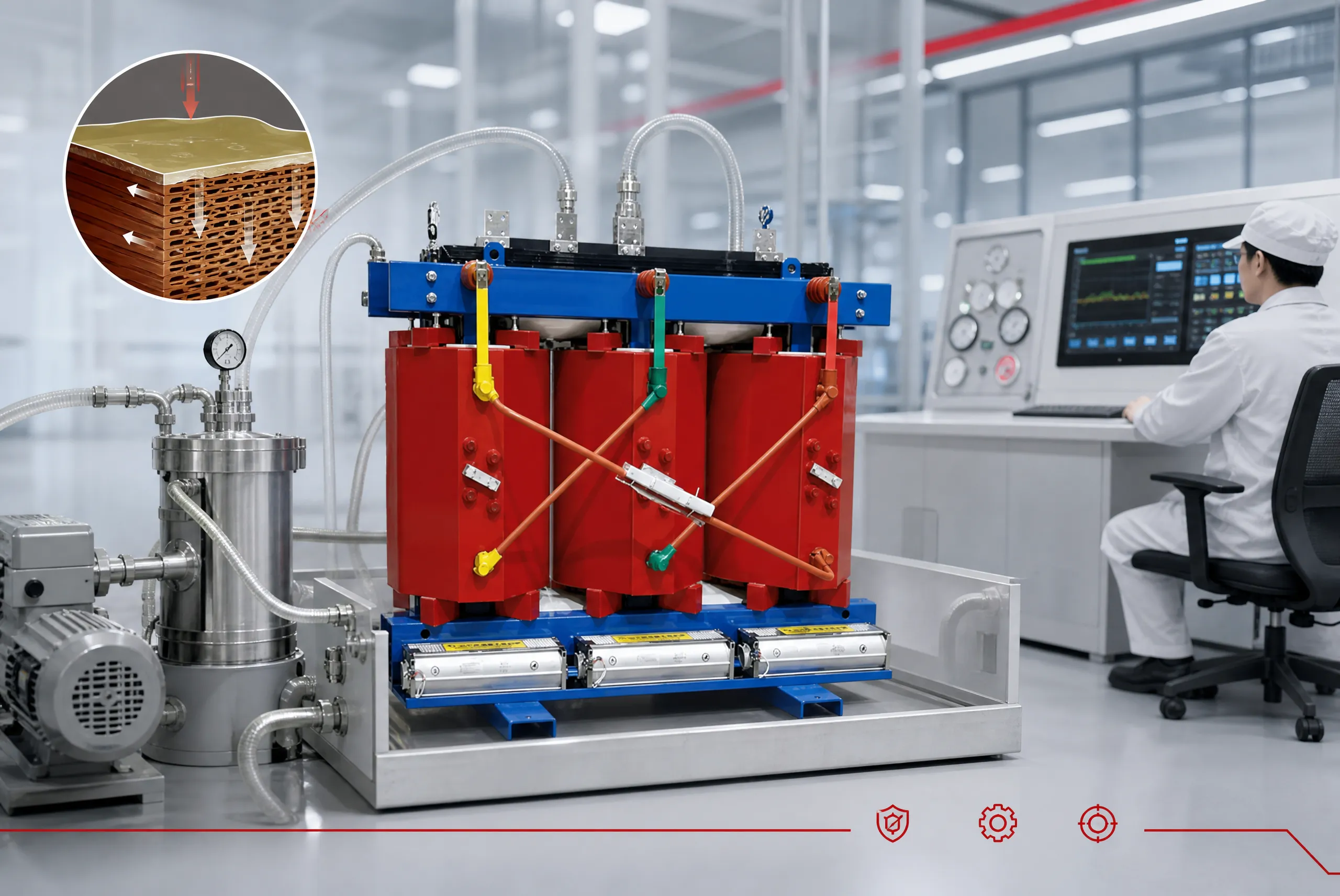
Impact Resistant Winding Manufacture – Using Grain Oriented Silicon Steel and then Using Epoxy Cast to Vacuum.
Once you determine the electrical specifications of the transformer, the permanent strength of the transformer exists within the winding. For the core, 0.23 mm grain-oriented silicon steel (for example, Nippon Steel or POSCO grade) in a step-lap stacked construction will reduce losses and magnetostrictive noise to comply with the MSHA regulations for underground mining.
The copper foil is very wide and made from DuPont™ Nomex® meta-aramid paper, providing Class H insulation to the low volage winding that feels the most electrodynamic forces and has sufficient thermal margin for the effects of harmonic heating (200 °C at the hot spot).
A total vacuum epoxy cast is produced on the complete winding. The vacuum epoxy casting process uses three stages that have been precisely controlled and therefore forms a reliable process.
- Vacuum degassing: In order to remove moisture, (or other trapped air) from the insulation layers around the wires of the winding, the winding is preheated to 60-80ºC and evacuated to less than 100 Pa. This process takes out all the moisture and other trapped air from the micro voids which ultimately lead to partial discharge.
- Pressure impregnation: Liquid epoxy resin infiltrates the tiniest spaces between the turns and layers through the application of a pressure difference. This creates an uninterrupted void-free body of insulating material with mechanical strengths that are multiples of that of a typical coil; and provides an insulated body of insulation that is completely filled throughout.
- Staged curing: Crosslinking proceeds under stepped temperature control at 100–140 °C. This prevents shrinkage stress from damaging the insulation and ensures long‑term dimensional stability under thermal cycling.
The result is a monolithic structure that withstands repeated 5–7× inrush shocks and controls partial discharge below 5 pC—meaning virtually no internal voids and dramatically slowed insulation aging. EPRI studies indicate that such vacuum‑cast dry‑type transformers can achieve over 15 years of fault‑free operation in harsh environments.
Protective Enclosures and OEM Customization — Solutions for Explosion Protection, Salt Spray, and High Altitude
The epoxy‑cast body resists moisture and flame, but the external enclosure must match the environment.
In underground coal mines, enclosures require MSHA or IECEx explosion‑proof certification. In coastal steel mills or open‑pit copper mines, a sealed stainless‑steel enclosure rated IP55 and NEMA 4X, with an anti‑condensation heater, defends against salt spray and conductive dust. The protective capability of a NEMA 4X enclosure can be understood across four distinct levels:
- Dust exclusion: The enclosure completely prevents the ingress of external dust, including conductive metallic particles.
- Water resistance: It withstands water jets from any direction, ensuring internal dryness during cleaning or heavy rain.
- Corrosion resistance: Fabricated from 304 or 316 stainless steel, it resists salt spray and acidic gases without requiring surface coatings.
- Condensation control: A built‑in thermostatically controlled heater prevents internal moisture condensation during temperature swings.
| Application Scenario | Primary Threat | Recommended Protection | Enclosure Features |
|---|---|---|---|
| Underground coal mine | Methane, high humidity | MSHA/IECEx flameproof | Flameproof, anti‑condensation heater |
| Coastal steel mill | Salt spray, metallic dust | IP55 + NEMA 4X | 304/316 SS sealed enclosure |
| Open‑pit copper mine | Conductive dust, heavy rain | IP55 | Stainless steel, air filters |
| High‑altitude (>4000m) | Low pressure, cooling difficulty | Derating per IEC 60076 | Increased creepage, high‑altitude fans |
At high‑altitude sites above 4 500 meters, IEC 60076 derating and increased clearances are mandatory. This is where OEM customization proves its value. We supply non‑standard voltage taps, specified cable entry positions, skid‑mounted bases, and remote temperature monitoring modules that interface with the plant DCS, seamlessly integrating into the existing distribution scheme.
Quality Assurance Closed Loop — IEEE/IEC Type and Special Tests with Third‑Party Data
Routine tests (ratio, DC resistance, power‑frequency withstand) are the baseline; only type and special tests confirm true “industrial‑grade” reliability. We adhere to IEEE C57.12.01 and IEC 60076 series standards, testing representative units beyond conventional requirements.
| Test Category | Examples | Purpose | Standard Basis | Third‑Party Witness |
|---|---|---|---|---|
| Routine | Ratio, DC resistance, power‑frequency withstand | Per‑unit consistency | IEC 60076‑11 | No (in‑house) |
| Type | Temperature rise, lightning impulse | Design and insulation validation | IEEE C57.12.01 | Recommended |
| Special | 2‑s short‑circuit withstand, partial discharge, sound level | Extreme‑condition reliability | IEC 60076‑5, IEEE C57.12.90 | Mandatory |
The temperature rise test verifies hotspot safety margin; lightning impulse tests check insulation robustness. Most decisive is the 2‑second short‑circuit mechanical withstand test, the “gold standard” for three compelling reasons:
- Extreme electrodynamic stress: With the secondary short‑circuited and rated voltage applied, windings experience peak forces hundreds of times greater than normal operation within milliseconds, directly testing the structural design’s ultimate margin.
- Comprehensive structural examination: The test simultaneously stresses core clamps, insulation blocks, lead supports, and fastening bolts—not just the windings—exposing any weak point.
- Rigorous acceptance criteria: Post‑test, turns ratio, impedance, and insulation resistance must remain unchanged, and a core‑and‑coil inspection must confirm zero permanent deformation.
A witnessed report from KEMA Laboratories or UL Solutions—and for routine production audits, our in‑house testing procedures adhere to IEC 60076 requirements and follow ISO/IEC 17025 principles—is the key document in technical evaluations. As a manufacturer with ISO 9001 certification and State Grid qualification, we apply consistent quality control at every step—from silicon‑steel incoming inspection and epoxy ratio monitoring to digital insulation resistance recording. Ongoing R&D efforts have produced multiple patents in winding heat dissipation and noise reduction, enabling a wide range of custom solutions. Advanced foil winding, vacuum casting, and automated testing lines support manufacturing precision and repeatability.
Case Study: Zambian Copper Mine Project
In a recent expansion at the Luanshya copper mine in Zambia, the site needed a transformer to withstand repeated 5× starting surges for a SAG mill, at altitude with sulfurous dust.
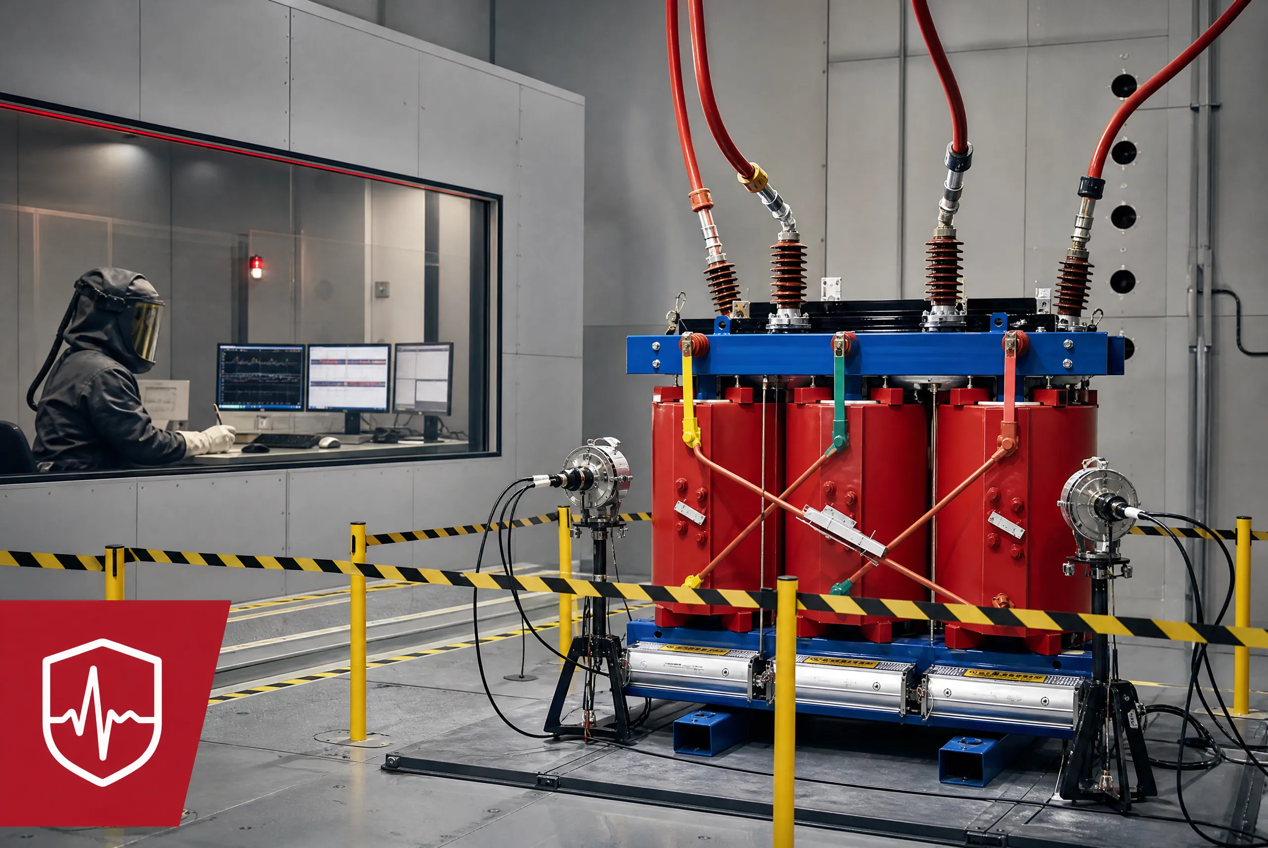
We supplied a 6.3 MVA, 33/0.69 kV epoxy‑cast dry‑type unit with 8 % impedance, vacuum‑cast windings, and IP55 NEMA 4X enclosure. Our field engineers worked alongside the mine’s maintenance team during commissioning to verify harmonic damping and set the OLTC range, ensuring the sub‑2 % voltage fluctuation target was met from day one. The unit passed short‑circuit and temperature rise type tests at an accredited South African laboratory and has since maintained secondary voltage within ±2 % (contract required ±5 %) over 18 months of continuous operation. This confirms the value of full‑chain quality control from engineering to test verification.
Remote Mine Delivery and Lifecycle Support — From Shock‑Resistant Packaging to RCM Training
Transformer value is realized in the field. For remote sites in Mongolia, the Pilbara, or West Africa, logistics is an engineered task. We use ISO 2244‑compliant packaging, split‑core structures for shaft lowering, and nitrogen‑sealed ocean shipping with desiccant breathers to prevent condensation.
On site, detailed installation manuals and remote video support aid local teams. We also provide Reliability‑Centered Maintenance (RCM) training, helping users transition to condition‑based practices. This full‑lifecycle engagement is what groups like Freeport‑McMoRan and ArcelorMittal evaluate, distinguishing a long‑term technology partner from a one‑time vendor.
Call to Action
When selecting heavy‑duty step‑down transformers, look beyond the purchase price. Request a Total Cost of Ownership (TCO) calculation based on local tariffs and third‑party type test reports for short‑circuit withstand. We are committed to sustainable manufacturing and are glad to share operational loss data. To receive our Industrial Transformer Efficiency Selection and TCO White Paper or arrange a no‑obligation technical discussion, please contact our engineering team.
Frequently Asked Questions (FAQ)
References
- IEA (2023), World Energy Investment 2023, IEA, Paris. https://www.iea.org/reports/world-energy-investment-2023
- IEEE Std C57.12.01-2020, IEEE Standard for General Requirements for Dry-Type Distribution and Power Transformers. https://ieeexplore.ieee.org/document/9293244
- IEC 60076-11:2018, Power transformers – Part 11: Dry-type transformers. https://webstore.iec.ch/publication/28143
- IEC 61000-4-15:2010, EMC – Part 4-15: Flickermeter. https://webstore.iec.ch/publication/4235
- NEMA 250-2020, Enclosures for Electrical Equipment. https://www.nema.org/standards/view/enclosures-for-electrical-equipment
- ISO 2244:2000, Packaging – Horizontal impact test methods. https://www.iso.org/standard/31362.html
- EPRI (2009), Dry-Type Transformer Reliability in Industrial Environments, Report No. 1016472. https://www.epri.com/research/products/1016472