Low voltage describes the electrical range used for most building services, industrial loads, and final distribution. The exact boundary depends on the governing standard and jurisdiction. In IEC terminology, low voltage is generally up to 1,000 V AC or 1,500 V DC; extra-low voltage occupies the lowest portion of that range. Designers must use the definitions adopted by the project authority rather than assume one worldwide threshold.
What voltage is considered low voltage?
Common low-voltage systems include 400/230 V and 415/240 V three-phase networks, 480/277 V services, and 208/120 V systems. These voltages can deliver very high fault energy and remain hazardous. “Low” only distinguishes the class from medium and high voltage; it does not mean safe to touch.
Extra-low voltage typically includes control, signaling, communication, and selected safety circuits. SELV and PELV systems use specific source, separation, grounding, and voltage requirements to limit shock risk. A nominal 24 V control circuit can still cause fire or equipment damage if conductors and protection are incorrectly selected.
How a low-voltage distribution system works
A transformer supplies a main low-voltage switchboard. The main breaker feeds busbars, which distribute power through feeder breakers to motor control centers, distribution boards, panels, machinery, and final circuits. Metering, automatic transfer, power-factor correction, surge protection, and monitoring may be integrated according to the facility.
Equipment such as a prefabricated substation can place the transformer and low-voltage distribution close to the load center, reducing cable length and voltage drop.
Quick Comparison and Selection Table
Use this table as a quick review of the main engineering and procurement decisions explained in the article.
| Decision area | Practical meaning | What to verify |
|---|---|---|
| What voltage is considered low voltage? | Common low-voltage systems include 400/230 V and 415/240 V three-phase networks, 480/277 V services, and 208/120 V systems. | These voltages can deliver very high fault energy and remain hazardous. |
| How a low-voltage distribution system works | A transformer supplies a main low-voltage switchboard. | The main breaker feeds busbars, which distribute power through feeder breakers to motor control centers, distribution boards, panels, machinery, and final circuits. |
| Switchboards, switchgear, panels, and terminal blocks | A low-voltage switchboard is a floor-mounted assembly that receives and distributes substantial power. | Low-voltage switchgear generally emphasizes compartmentalization, interrupting performance, maintainability, and defined assembly ratings. |
| Low-voltage design calculations | Begin with connected load, demand, diversity, duty cycle, starting current, power factor, and future expansion. | For balanced three-phase power, current is approximately I = P ÷ (√3 × V × PF × efficiency) . |
| Protection and coordination | Main and feeder breakers must interrupt the available fault current and coordinate so the device closest to a fault operates first where practical. | Protection can include overload, instantaneous short-circuit, short-time delay, ground fault, residual current, undervoltage, phase loss, and surge functions. |
Switchboards, switchgear, panels, and terminal blocks
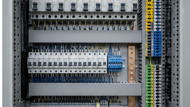
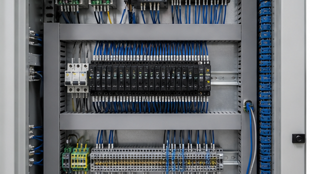
A low-voltage switchboard is a floor-mounted assembly that receives and distributes substantial power. Low-voltage switchgear generally emphasizes compartmentalization, interrupting performance, maintainability, and defined assembly ratings. A panelboard is commonly a smaller wall-mounted assembly for branch circuits. Terminology varies, so specifications should state ratings and functions rather than rely on the name alone.
Terminal blocks provide organized field connections for power, control, neutral, and protective conductors. Select them for conductor material and size, current, voltage, short-circuit withstand, temperature, and required accessories. Keep power and sensitive signal circuits separated where electromagnetic interference matters.
Low-voltage design calculations
Begin with connected load, demand, diversity, duty cycle, starting current, power factor, and future expansion. For balanced three-phase power, current is approximately I = P ÷ (√3 × V × PF × efficiency). For single-phase loads, use I = P ÷ (V × PF × efficiency). These values establish a starting point, not the final protective-device setting.
Check voltage drop during normal operation and motor starting, conductor ampacity after derating, neutral current from nonlinear loads, prospective short-circuit current, protective-device breaking capacity, selectivity, arc energy, and earth-fault loop performance. A low voltage and high current combination demands robust busbars and short, well-supported connections.
Protection and coordination
Main and feeder breakers must interrupt the available fault current and coordinate so the device closest to a fault operates first where practical. Protection can include overload, instantaneous short-circuit, short-time delay, ground fault, residual current, undervoltage, phase loss, and surge functions. Settings must match conductors, equipment withstand curves, and operating needs.
Safety and construction requirements
Specify rated assemblies, correct enclosure protection, internal separation, mechanical interlocks, shutters where applicable, protective earthing, neutral arrangement, access clearances, ventilation, and labeling. Arc-flash risk depends on fault current, clearing time, working distance, and enclosure—not merely nominal voltage.
Installation checks should cover cable bend radius, lug compatibility, torque, phase sequence, insulation resistance, continuity, breaker operation, trip tests, control logic, metering, and grounding. Products such as GGD low-voltage fixed switchgear must be selected against the project’s system current, fault level, form of separation, environment, and service needs.
Maintenance priorities
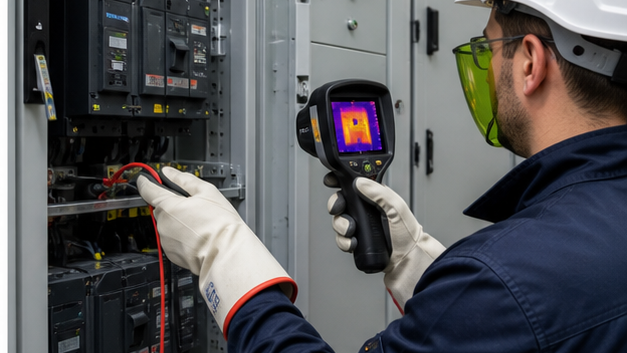
Keep assemblies clean and dry, inspect for heat damage and corrosion, test protective functions at planned intervals, exercise mechanisms, review event logs, and trend temperatures under comparable loads. Investigate hot joints, repeated trips, insulation deterioration, and unusual noise before they become failures. Any energized work requires a documented risk assessment and authorized procedures.
Low-voltage power and telecommunications are different scopes
In building practice, “low voltage” sometimes describes communications, fire alarm, security and data cabling, while power standards use the term for a defined electrical voltage range. Project documents must state which meaning applies so power distribution and extra-low-voltage systems are not confused.
Low voltage still has significant fault energy
A 400/480 V board can deliver very high short-circuit current and arc energy. Equipment rating, conductor protection, earthing, isolation and safe working procedures remain essential. Lower nominal voltage reduces insulation distance but does not make an energized system harmless.
Technical references and further reading
The following independent sources support the standards, terminology, calculations, and safety context discussed in this guide:
- NIST SI units for electric current — Authoritative definitions and relationships for amperes, volts, watts, and ohms.
- NIST Guide to SI electrical conversion factors — Official conversion factors for electricity, magnetism, energy, and related quantities.
- OSHA electrical safety requirements — Safety context for applying electrical calculations to transmission and distribution work.