Pad mounted switchgear manufacturers should be qualified against the proposed equipment class, distribution circuit and site interfaces before their quotations are compared. A green outdoor enclosure is not proof of suitable switching functions, fault capability or access arrangements. Begin with the project single-line drawing, installation conditions and required verification records. This guide explains how to turn those inputs into a manufacturer review, including enclosure scope, cable interfaces, operating functions and final documents. It does not rank companies or invent current market shares. The product illustrations are exterior references, not proof of a particular project’s electrical performance.
Define what pad mounted means on this project
The phrase generally describes equipment installed in an outdoor enclosure at ground level on a prepared support. It describes an installation form, not one universal circuit arrangement. The assembly may contain different switching, protection and isolation functions depending on the distribution network. Confirm the actual equipment class and the governing specifications rather than treating the name as a complete technical requirement.
Distinguish switchgear from a packaged transformer substation or other outdoor distribution equipment. A manufacturer that offers one category does not automatically provide every other category in the same form. Ask for a drawing of the offered assembly, its circuit functions and the proposed boundary with the civil works. The quotation should identify the equipment supplied inside the enclosure and any equipment supplied by others.
Start manufacturer review with the circuit
Provide the number and role of incoming and outgoing circuits, transformer feeders if applicable, normal operating arrangements and any required alternate supply arrangement. Identify the intended switching and protection functions. A cabinet photograph cannot answer those questions. The responsible engineer must define them using the network design and the project’s operating needs.
Ask each manufacturer to map its proposed assembly to that design. A clear response identifies circuit positions and functions without relying on model names alone. Record any deviations, including arrangements that need extra equipment or a changed operating sequence. This makes the technical review useful before commercial comparisons begin and reduces the chance of ordering an enclosure with the wrong functional contents.
| Qualification area | Evidence to request | Decision it supports |
|---|---|---|
| Assembly scope | Circuit diagram, equipment class and proposed functions | Whether the offer fits the network |
| Electrical duties | Project ratings and relevant verification records | Whether the design basis is supported |
| Site interface | Arrangement, support and cable entry drawings | Whether equipment and civil works align |
| Access and operation | Door, locking, operating and maintenance requirements | Whether the location supports safe use |
| Delivery and support | Document programme, spare scope and service boundary | Whether the project can accept and maintain the assembly |
Verify the actual assembly rather than a general brand claim
Ask how the proposed equipment has been verified for the applicable assembly requirements. The relevant evidence should identify the design and its scope. A manufacturer’s general quality certificate describes a management system; it does not establish every rating or performance claim for a specific switchgear configuration. Likewise, a component’s rating is not automatically the rating of the complete assembly.
The IEC metal-enclosed AC switchgear publication supplies a standards context for equipment within its stated scope. A project may also have utility, national or contractual requirements. The review should identify the applicable edition and arrangement. If evidence refers to another configuration, ask the manufacturer to explain its relevance and limitations instead of accepting a document cover page as complete proof.
Civil and enclosure interfaces deserve early attention
Ground-level equipment needs coordinated support, anchoring, cable access and working space. The manufacturer’s arrangement drawing should show the dimensions and interfaces needed by the civil designer. State who supplies the support and who verifies its suitability. A late change to cable entry or enclosure access can affect the prepared site even when the electrical diagram remains unchanged.
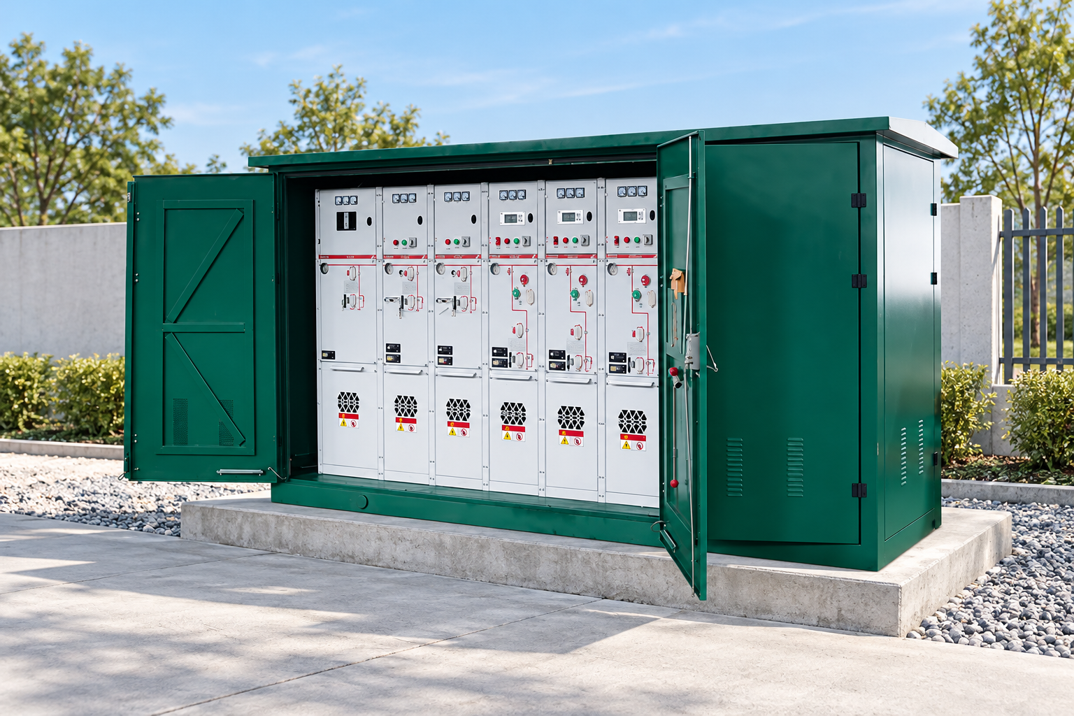
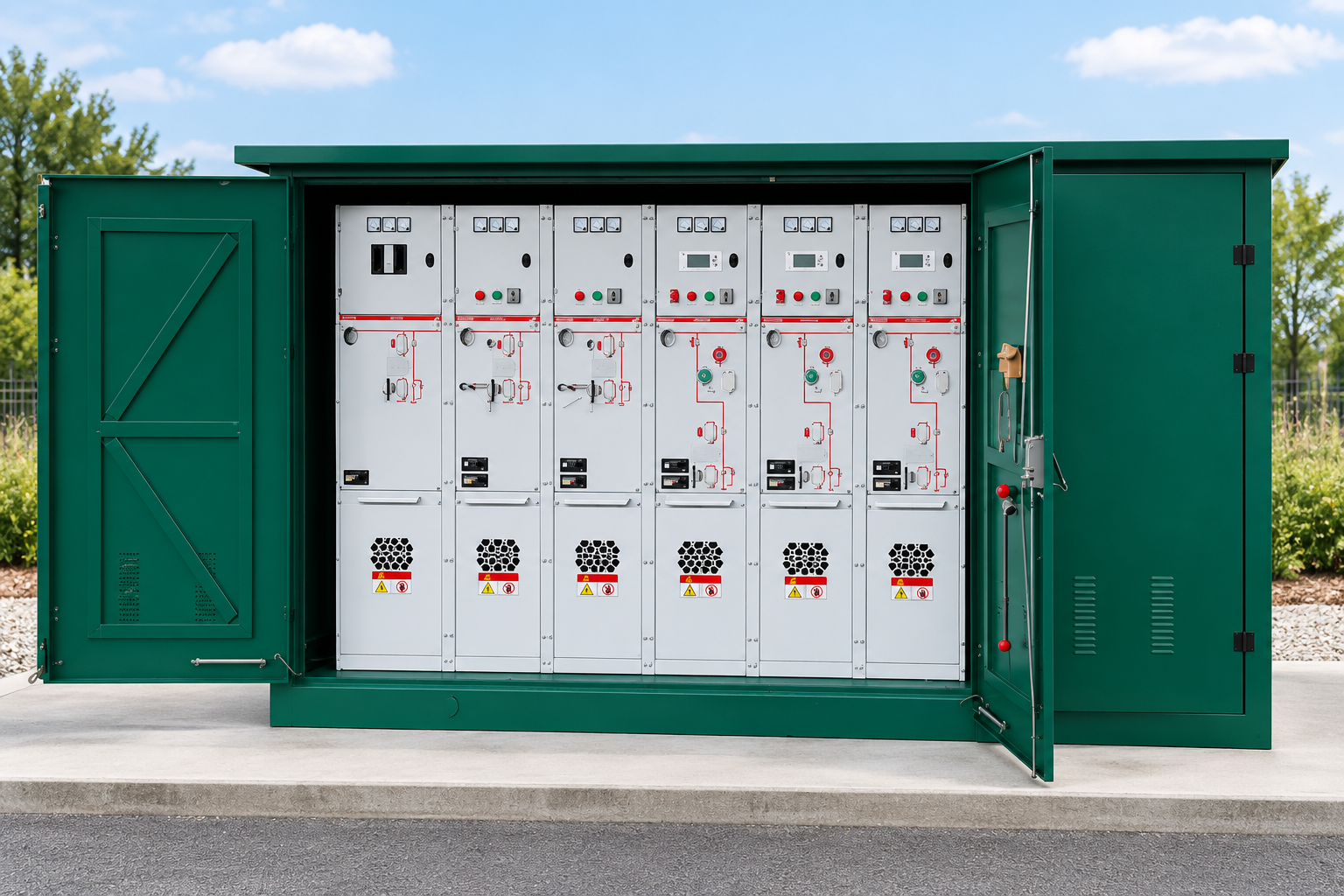
The LBAJI XGW product reference shows an outdoor enclosure with accessible cabinet fronts. That exterior helps illustrate why door movement and working space matter. It does not define a standard foundation detail or establish suitability for every outdoor site. Obtain the actual project drawing and installation requirements before construction. Do not scale measurements from an illustration or infer internal clearances from a brochure image.
Specify the environment in usable terms
Describe ambient conditions, moisture, dust, corrosion exposure, flooding concerns and other relevant site features. The project’s required enclosure protection and materials should be explicit. General terms such as outdoor type are too vague to support acceptance. Ask the manufacturer to identify environmental limits and any restrictions on mounting, ventilation or maintenance.
A site may need additional measures outside the supplied equipment. These can include drainage, protection from physical damage or a particular access arrangement. Assign those responsibilities in the scope. Do not assume that an enclosure rating resolves every site hazard. The design team should review the complete installation, and the manufacturer’s instructions should remain part of that review.
Cable interfaces can determine whether equipment fits
State cable types, quantities, termination requirements and routing assumptions through the approved design process. The manufacturer should identify the supported connection arrangement and the space or access requirements for installation and maintenance. The civil and cable teams need those details before their work is finalized. A nominal voltage match does not prove that the actual cable interface is suitable.
Where separable connectors or other specific termination systems are used, document the required interface and the party supplying the terminations. Do not assume compatibility from a similar connector shape. Changes must be reviewed against the proposed equipment and cable system. The final drawing should resolve those interfaces rather than leaving the installer to select an unapproved workaround at delivery.
Review operation and protection as separate functions
A switching function, an isolation function and fault interruption are different duties. The chosen assembly may use combinations of devices to perform them. Ask the manufacturer to explain how each required circuit function is provided. The project protection review should establish the relevant settings and coordination; a basic enclosure proposal cannot complete that work.
Also identify manual or remote operation, auxiliary supply and indication requirements. If remote monitoring is included, specify its communication and control boundaries. A communications port is not evidence that the utility or plant system will operate the equipment correctly. Allocate configuration, integration and acceptance responsibilities before the procurement decision so that the offered package can be compared consistently.
Access arrangements are a project requirement
Door opening, locks, operating positions and maintenance access must suit the planned location and the applicable rules. Where unauthorized access is a concern, state the required measures in the specification. Ask for the actual enclosure arrangement and approved instructions. Avoid treating a visible padlock fitting as proof that all site access requirements are satisfied.
The equipment must be operated and maintained by appropriately qualified personnel under the relevant procedures. Applicable OSHA electrical work-practice requirements provide one U.S. safety framework; local rules and utility procedures may add or differ in requirements. This guide does not prescribe field switching steps. Manufacturer qualification should confirm that the necessary instructions and training boundaries are available for the proposed assembly.
Compare manufacturer responsibilities explicitly
A manufacturer may design and assemble the switchgear while another contractor owns protection studies, civil works or commissioning. Write these boundaries into the review. Ask who provides the final drawings, component records, test reports and installation instructions. The buyer should know which organization closes each technical question rather than assuming the equipment supplier owns the entire network project.
Request a deviation schedule with the offer. A stated deviation can be reviewed; a hidden assumption can become a site problem. Keep accepted changes attached to the purchase specification and drawings. The manufacturer should confirm the resulting configuration before production. This is especially useful when several suppliers use different standard arrangements to answer the same inquiry.
Use factory acceptance to close the agreed scope
Define the factory acceptance requirements and document review in the purchase agreement. The inspection should relate to the actual ordered assembly, not a generic demonstration cabinet. Record identification, agreed checks, findings and corrective actions. Factory acceptance provides evidence within its scope; it does not replace all design verification, site checks or network commissioning.
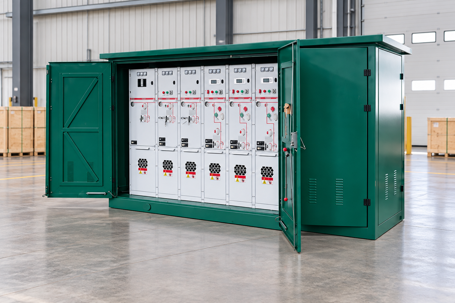
Plan how unresolved findings will be closed before shipment. If photographs are used for a remote review, define what they can and cannot establish. A photograph of a closed lineup cannot prove internal workmanship or every functional condition. The acceptance process should rely on the agreed records, qualified checks and documented decisions rather than on a delivery deadline alone.
Assess maintainability and delivery evidence
Ask about replacement components, maintenance instructions and the support available for the proposed design. Identify which parts are shared across units only when interchangeability is documented. For a critical network location, review the consequences of a long replacement lead time. A general statement about spare availability is less useful than a specific support scope for the ordered assembly.
Delivery timing should identify approval milestones, component availability, packing and shipping boundaries. Request the final document programme alongside the fabrication programme. A cabinet that arrives before its accepted drawings and records can still delay the project. The best manufacturer response makes those dependencies visible and gives the buyer a clear basis for technical and commercial acceptance.
Frequently asked questions
Does a green outdoor enclosure prove equipment is pad mounted switchgear?
No. Installation form, circuit functions, assembly class and project scope must be established from the manufacturer’s documents.
Can I qualify a manufacturer from a quality certificate alone?
No. Request evidence relevant to the proposed assembly and its specified duties, as well as project drawings and a deviation schedule.
Who should design the foundation and cable routes?
The project must assign those responsibilities. The manufacturer provides the necessary equipment interface requirements, while qualified designers coordinate the complete installation.
Does factory acceptance replace site commissioning?
No. Factory acceptance has an agreed scope; transport condition, installation interfaces and network operation still require appropriate site checks.
What should a first inquiry contain?
Include the single-line drawing, circuit functions, electrical duties, environment, cable and civil interfaces, document requirements and desired programme.
Technical references and related equipment
The linked standards pages describe their scope; project compliance requires the applicable documents and engineering review.
- IEC metal-enclosed AC switchgear scope
- 29 CFR 1910.333 electrical work practices (official 2025 edition)
- LBAJI XGW-12/630-25 Ring Main Unit
- switchgear fundamentals
- switchgear verification and testing
- switchgear maintenance planning
Further learning: equipment fundamentals
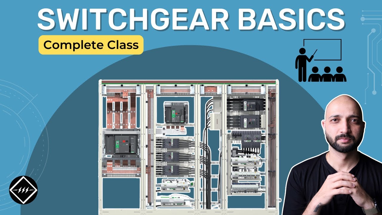
This independent educational video supports the background discussion of equipment functions. It does not replace approved project documents or qualified electrical work procedures. Source: Gaurav J – TheElectricalGuy.
Watch Switchgear Basics: Complete Beginner's Guide | TheElectricalGuy