Photovoltaic warning labels identify multiple power sources, energized DC conductors, disconnects, rapid-shutdown controls, arc-flash or shock hazards, and emergency information at the exact equipment and access points required by the adopted electrical and fire codes.
Key Takeaways
- Identify the exact duty and system boundary before selecting equipment.
- Verify ratings, protection, environment, interfaces, and maintainability together.
- Use qualified personnel and project-specific standards for final decisions.
Quick Selection Table
| Decision area | Practical meaning | Project check |
|---|---|---|
| Start with the adopted code | Label content and location vary by jurisdiction and code edition. | Record the authority having jurisdiction, adopted code editions and applicable equipment instructions. |
| Map every source and disconnect | Trace modules, combiners, DC disconnects, inverters, AC disconnects, batteries, generators, service equipment, meters, and interconnected feeders. | Compare the approved one-line and as-built drawing; note each source, disconnect and conductor state after shutdown. |
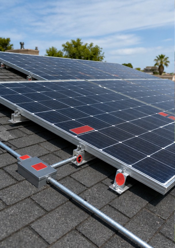
| Typical PV label locations | Common locations include service equipment, meter positions, PV system disconnects, raceways with PV DC conductors, combiner boxes, inverter inputs and outputs, rapid-shutdown initiators, battery enclosures, and directories or plaques showing source locations. | Verify required points against adopted rules and drawings; check visibility and responder access on site. |
| Wording, colors, and symbols | Use the exact signal words, legends, colors, letter height, contrast, and symbols required for the applicable condition. | Use the approved compliance schedule’s exact text and artwork; do not assume a generic label kit is compliant. |
| Durability and attachment | Select material and adhesive for sunlight, heat, cold, moisture, chemicals, salt, and the equipment surface. | Match the label, adhesive and attachment method to the surface, UV, moisture, heat, cold and chemical exposure. |
| Rooftop and emergency response information | Provide access pathways, array boundaries, rapid-shutdown control identification, and a site plan or directory where required. | Coordinate array maps, rapid-shutdown identifiers and access information with the adopted fire rules and local responders. |
Start with the adopted code
Label content and location vary by jurisdiction and code edition. Identify the authority having jurisdiction, utility rules, building and fire code, equipment listing instructions, and project standard before printing labels. A generic online kit is not a compliance plan.
Map every source and disconnect
Trace modules, combiners, DC disconnects, inverters, AC disconnects, batteries, generators, service equipment, meters, and interconnected feeders. Marking must help an operator or responder understand which conductors remain energized and which device controls them.
PV conductors can remain hazardous under some sunlight and shutdown conditions. Show responders where PV-connected conductors and system components are located, and verify the actual shutdown boundary from the approved design rather than treating a label as proof that a circuit is de-energized.

Typical PV label locations
Common locations include service equipment, meter positions, PV system disconnects, raceways with PV DC conductors, combiner boxes, inverter inputs and outputs, rapid-shutdown initiators, battery enclosures, and directories or plaques showing source locations.
For a label order, give the adopted code edition, approved text and symbols, drawing location, substrate, exposure, quantity, sample-approval method and installation responsibility. Have the owner or authority review any code-dependent wording before production.
Wording, colors, and symbols
Use the exact signal words, legends, colors, letter height, contrast, and symbols required for the applicable condition. Do not substitute a marketing phrase for mandated wording. Keep emergency shutdown directions short, unambiguous, and consistent with the as-built system.
Durability and attachment
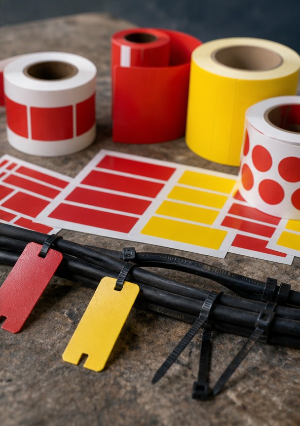
Select material and adhesive for sunlight, heat, cold, moisture, chemicals, salt, and the equipment surface. Printed characters must remain legible for the expected environment. Mechanical attachment may be needed where adhesive performance is uncertain.
Rooftop and emergency response information
Provide access pathways, array boundaries, rapid-shutdown control identification, and a site plan or directory where required. Responders need a clear way to identify PV-connected conductors and component locations; the U.S. Department of Energy’s solar fire-safety guide explains why this information helps crews locate the system.
Inspection and maintenance
Verify every label against the final drawings during commissioning. Inspect after reroofing, inverter replacement, expansion, weather exposure, or equipment repainting. Remove obsolete labels so two contradictory instructions are never visible.
Label schedule for an RFQ
Create a schedule with unique identifier, exact text, code reference, material, color, size, mounting method, quantity, and installation location. Link each entry to the drawing and require final photographic records.
Practical Specification Workflow
- Record the project jurisdiction, authority having jurisdiction and adopted electrical/fire code editions.
- Collect the approved one-line diagram, equipment list, shutdown sequence and current as-built drawings.
- Map every PV, storage, utility and other source, including the conductors that may remain energized in each isolation state.
- For each required mark, list its drawing location, exact approved wording, reference, symbol, material and quantity.
- Confirm label size, contrast, environmental durability and attachment method against the rule and installation surface.
- Submit the schedule and sample artwork for project/authority review before bulk production.
- Install at approved locations, inspect visibility and accuracy, then retain photographs and the final label schedule.
How to Review a Supplier Submittal
Begin with a compliance matrix instead of a brochure. Check every requested rating and interface against the supplier drawing, data sheet, calculation, and test plan. Confirm that stated values apply to the offered configuration, enclosure, ambient temperature, altitude, and accessories. Resolve exclusions involving protection, terminals, controls, monitoring, installation, commissioning, and spare parts before approval. Where a standard permits alternatives, record which option has been supplied.
Next, test the proposal against credible operating events: maximum and minimum voltage, peak load, starting or energization, external fault, loss of cooling, maintenance isolation, communication failure, and the planned contingency. Confirm access for inspection and component replacement. Require final as-built drawings, nameplate schedules, routine-test reports, settings, manuals, and a clear warranty contact. This review prevents a technically plausible product from arriving with the wrong interfaces or incomplete scope.
Related LBAJI Resources
Review the relevant LBAJI equipment page, the main technical guide, and the related articles on system selection and safety and installation or application planning. For a quotation, provide the one-line diagram, ratings, quantity, environment, and required standards.
Frequently Asked Questions
Do photovoltaic warning-label requirements vary by location?
Yes. The locally adopted electrical and fire-code editions, amendments, authority having jurisdiction and listed-equipment instructions control the required wording and placement. Confirm these before ordering labels.
Can PV conductors remain hazardous after a disconnect is opened?
Some conductors may remain energized in sunlight or outside a rapid-shutdown boundary. The exact boundary depends on the system design and applicable rules; follow the approved shutdown sequence and never use a label as proof of safe isolation.
What belongs in a PV warning-label schedule?
Record each label’s exact approved text or symbol, code reference, drawing location, material, size, attachment method, quantity and installation responsibility.
How should outdoor PV labels be selected?
Check the substrate and exposure to sunlight, heat, cold, moisture, chemicals and cleaning. The complete label and attachment must remain legible in the actual environment and satisfy project requirements.
When should PV labels be inspected?
Verify them against approved drawings at commissioning and recheck after system changes, equipment replacement, reroofing, repairs or visible damage. Keep the final schedule and location photographs with the as-built record.
Technical References
Conclusion
Photovoltaic warning labels identify multiple power sources, energized DC conductors, disconnects, rapid-shutdown controls, arc-flash or shock hazards, and emergency information at the exact equipment and access points required by the adopted electrical and fire codes. Final selection, installation, testing, and maintenance must be based on project data and approved procedures rather than a general web guide.