A power factor correction capacitor supplies reactive power close to an inductive load, reducing the reactive current drawn from the utility. Correctly applied, a capacitor bank can lower current, release transformer and cable capacity, reduce losses, and help avoid utility penalties. The design must match the real load profile and harmonic environment; simply installing the largest available bank can create overcorrection, resonance, or equipment damage.
What power factor correction changes
Power factor is the ratio of real power in kilowatts to apparent power in kilovolt-amperes: PF = kW ÷ kVA. Motors, transformers, welders, and discharge lighting consume inductive reactive power. A capacitor produces reactive power in the opposite direction, so the upstream system carries less unnecessary current while the useful kW remains essentially unchanged.
The main advantages of power factor correction are lower line current, reduced voltage drop and I²R losses, more usable capacity in transformers and switchgear, and possible reduction of demand charges. It does not directly reduce the energy consumed by the mechanical load, and it cannot correct poor efficiency or load imbalance.
How to size a capacitor bank
For a known real load, the required correction is commonly estimated with Qc = P × (tan φ1 − tan φ2), where P is load kW, φ1 is the angle at the existing power factor, and φ2 is the angle at the target power factor. For example, correcting 500 kW from 0.75 to 0.95 power factor requires approximately 277 kVAr. Final sizing should use measured demand intervals rather than only equipment nameplates.
A target such as 0.95 to 0.98 is usually safer than trying to maintain unity under every operating condition. If the load varies, divide the total kVAr into stages. The smallest stage determines the controller’s resolution, while a sensible stage sequence prevents constant switching around the target.
Quick Comparison and Selection Table
Use this table as a quick review of the main engineering and procurement decisions explained in the article.
| Decision area | Practical meaning | What to verify |
|---|---|---|
| What power factor correction changes | Power factor is the ratio of real power in kilowatts to apparent power in kilovolt-amperes: PF = kW ÷ kVA . | Motors, transformers, welders, and discharge lighting consume inductive reactive power. |
| How to size a capacitor bank | For a known real load, the required correction is commonly estimated with Qc = P × (tan φ1 − tan φ2) , where P is load kW, φ1 is the angle at the existing power factor, and φ2 is the angle at the target power factor. | For example, correcting 500 kW from 0.75 to 0.95 power factor requires approximately 277 kVAr. |
| Fixed, automatic, and fast correction methods | A fixed capacitor is suitable for a stable individual load, such as a continuously operated motor. | It should be switched with the load and checked against self-excitation limits. |
| Harmonics and detuned reactors | Capacitors and the upstream system inductance can form a resonant circuit. | Variable-frequency drives, UPS systems, rectifiers, and similar nonlinear loads may inject harmonics that are amplified at resonance. |
| Protection, switching, and installation | Capacitor current can exceed its nominal value because of voltage tolerance and harmonics. | Select cables, busbars, breakers, fuses, contactors, and reactors for the manufacturer’s specified continuous and inrush duties. |
Fixed, automatic, and fast correction methods
Fixed capacitors
A fixed capacitor is suitable for a stable individual load, such as a continuously operated motor. It should be switched with the load and checked against self-excitation limits. Fixed correction on a lightly loaded transformer or motor can produce a leading power factor.
Automatic capacitor banks
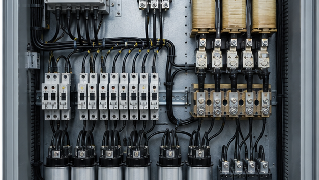
An automatic power factor correction capacitor bank uses a controller to add or remove contactor-switched stages. It is the usual choice for a main low-voltage distribution board serving multiple variable loads. The bank should coordinate with the incoming breaker and the site’s preinstalled substation capacity.
Thyristor-switched and active solutions
Rapidly fluctuating loads may need thyristor switching because conventional contactors cannot follow changes fast enough. Active power factor correction in electronic equipment and active harmonic filters use power electronics; these are different from a conventional shunt capacitor bank. The right power factor correction equipment depends on response time, harmonic spectrum, voltage, and load behavior.
Harmonics and detuned reactors
Capacitors and the upstream system inductance can form a resonant circuit. Variable-frequency drives, UPS systems, rectifiers, and similar nonlinear loads may inject harmonics that are amplified at resonance. Symptoms include capacitor overheating, fuse operation, contactor damage, voltage distortion, and shortened service life.
A harmonic survey should therefore precede design on an industrial system. Detuned reactors connected in series with capacitor stages shift the resonance below a troublesome harmonic and limit inrush current. Where distortion is severe, a filtered bank or active harmonic filter may be required. The bank must also be coordinated with medium-voltage switchgear and existing protective relays.
Protection, switching, and installation
Capacitor current can exceed its nominal value because of voltage tolerance and harmonics. Select cables, busbars, breakers, fuses, contactors, and reactors for the manufacturer’s specified continuous and inrush duties. Capacitor-duty contactors use pre-charge resistors or limiting arrangements to control switching transients.
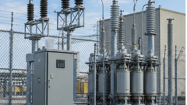
Provide discharge resistors, enclosure ventilation, earthing, warning labels, and adequate clearance. Temperature is especially important because capacitor life falls rapidly when the dielectric operates too hot. Medium-voltage banks may also require unbalance protection, surge arresters, dedicated switching devices, and interlocks compatible with equipment such as 40.5 kV metal-enclosed switchgear.
Commissioning and maintenance checklist
Before energization, verify capacitance, insulation, wiring, torque, earthing, fuse ratings, controller inputs, current-transformer polarity, and the discharge time. Energize stages individually and record current, voltage, kVAr, power factor, temperature, and total harmonic distortion. Confirm that the controller removes stages as load falls.
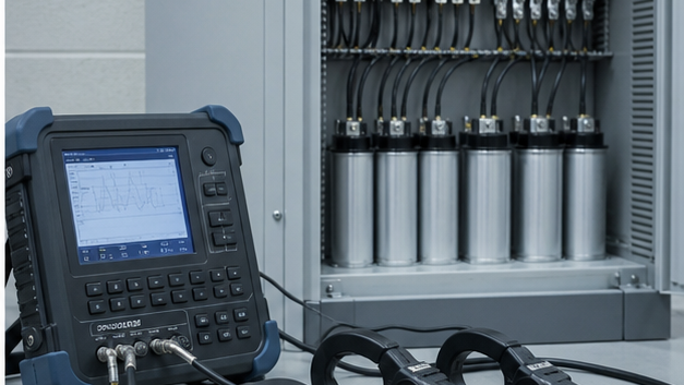
During service, inspect for bulging, leakage, discoloration, loose joints, failed fans, abnormal noise, unequal phase current, and repeated fuse operation. Trend power factor and harmonic readings rather than relying only on a controller display. A recurring failure is a system warning that requires investigation, not merely another replacement capacitor.
How to specify the right correction system
Provide the supplier with system voltage and frequency, measured kW/kVAr/PF profiles, transformer rating and impedance, short-circuit level, harmonic spectrum, load switching pattern, ambient conditions, enclosure requirements, available fault level, and desired target power factor. This information allows the manufacturer to select stage sizes, capacitor voltage rating, detuning, switching technology, protection, and ventilation as one coordinated system.
Power-factor improvement methods
Correction may be applied at an individual motor, a group board or the main bus. Fixed capacitors suit stable loads; automatic banks follow changing demand; dynamic or active systems suit rapid variation. Placement changes cable loading, switching frequency and the risk of overcorrection.
PFC capacitors in harmonic-rich systems
VFDs, UPS equipment and rectifiers can drive harmonic current into capacitors and create resonance with system inductance. Measure the spectrum and model the network before selecting a plain bank. Detuned reactors, higher capacitor voltage ratings or active filtering may be necessary, followed by commissioning measurements under representative load.
Technical references and further reading
The following independent sources support the standards, terminology, calculations, and safety context discussed in this guide:
- NIST SI units for electric current — Authoritative definitions and relationships for amperes, volts, watts, and ohms.
- NIST Guide to SI electrical conversion factors — Official conversion factors for electricity, magnetism, energy, and related quantities.
- OSHA electrical safety requirements — Safety context for applying electrical calculations to transmission and distribution work.