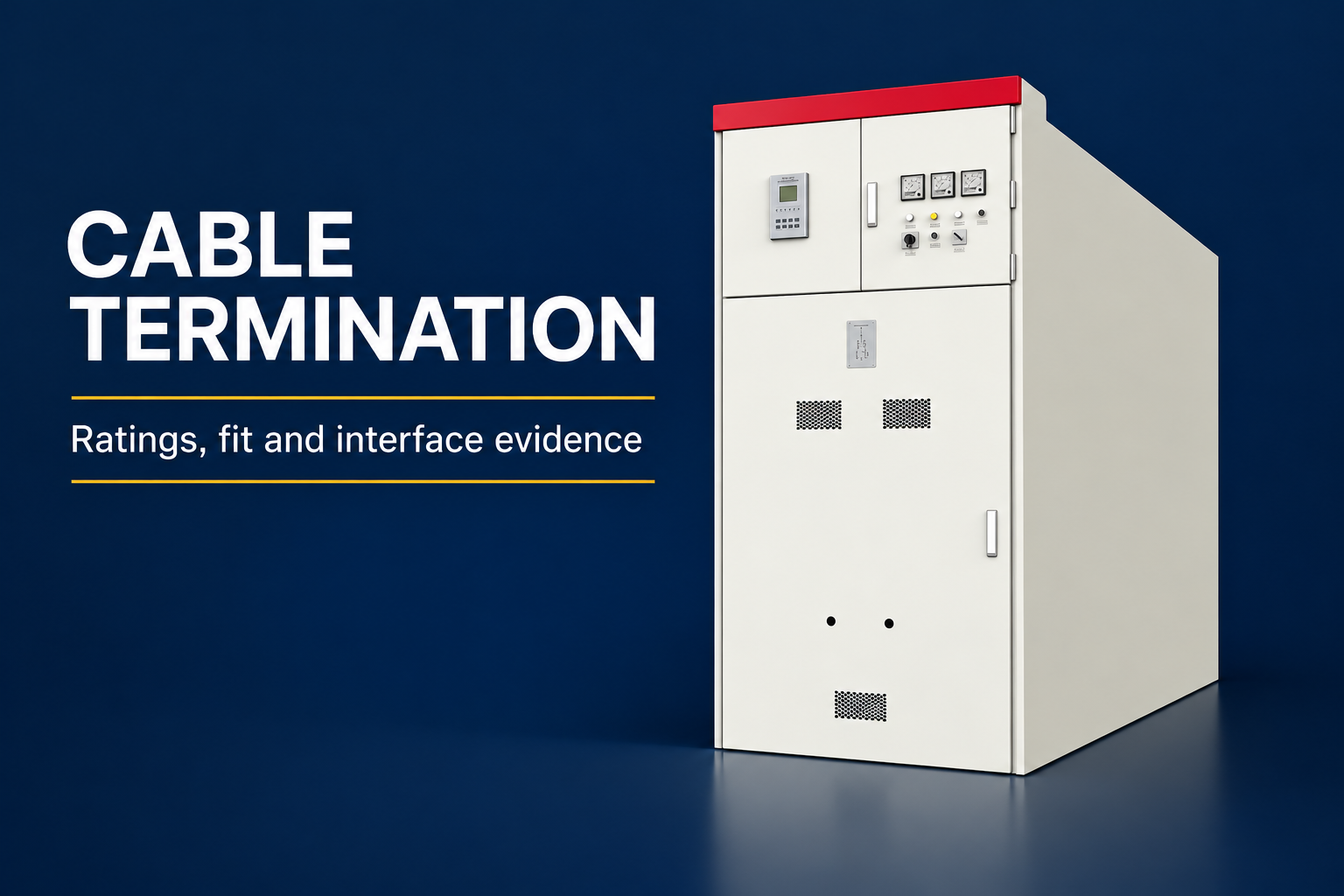
Switchgear room layout must accommodate the complete life of the equipment: delivery, installation, operation, inspection, component removal and future changes. Start with approved supplier drawings, the applicable installation requirements and the building’s actual constraints. A floor plan based only on cabinet width and depth can omit the working envelope, cable interfaces, escape routes and environmental services that make the room usable. This guide explains the coordination questions and records needed for a layout review; it does not assign universal clearances or replace qualified electrical, structural and building design.
Define the equipment and room boundaries
Identify every assembly and supporting system intended for the room. The switchgear footprint is only one part of the design. Protection panels, auxiliary supplies, building services and interface equipment may also require access and maintenance space. Establish the exact lineup arrangement, installation orientation and any supplier restrictions. A generic catalogue outline is not enough where the ordered configuration has different access, cable entry or service requirements.
Confirm which organization coordinates the room. Electrical designers, equipment suppliers, civil contractors and building-service designers can each produce a valid drawing that conflicts with another discipline. Appoint a coordination owner and agree the drawing revision used for the review. Record interfaces and unresolved items in one place. This creates a practical basis for deciding whether the room is ready for equipment delivery, instead of relying on separate approvals that never examine the combined installation.
Draw the full service envelope
Use the supplier’s drawings to identify door movement, access panels, withdrawable-device travel and component-removal needs. Include handling equipment and temporary service positions where required. The closed cabinet outline does not establish the space needed to maintain it. Ask how each significant component can be removed and transported out of the room under an approved method. A lineup that fits through the doorway during installation may still have an inaccessible replacement path later.
Compare the proposed layout with the applicable working-space and access requirements for the actual voltage class, task and jurisdiction. Do not borrow a dimension from an unrelated installation or infer a safe clearance from a generated image. The responsible engineer must establish the criteria. Mark the relevant envelopes on the coordinated drawing so that another contractor cannot accidentally place a pipe, cabinet or structural obstruction inside a space required for operation or maintenance.

Review the delivery route before the floor plan is frozen
The route begins at the unloading location and continues through doors, corridors, turns and any level changes to the final position. Confirm packed dimensions and shipment-specific handling requirements with the supplier. Distinguish the size of the bare equipment from the shipping unit and any handling envelope. The logistics method should be developed by competent parties using the actual mass, support and lifting information, rather than improvised after the equipment arrives.
Record temporary building conditions that affect the route. A planned removable panel, unfinished wall or temporary opening must have an owner and a completion sequence. Consider whether that route will still exist when a major component needs replacement years later. If the layout relies on dismantling building elements, make that assumption explicit and obtain the relevant approval. The room design should not quietly depend on an exceptional construction arrangement that the future operator will never know about.
Coordinate cable-entry interfaces
Cable arrangements affect trenches, ducts, support systems, termination space and access. Obtain the supplier’s approved entry and termination details together with the project’s actual cable information. Identify who supplies interface parts and who verifies their completion. A cable route drawn as a line on the room plan does not establish that the real cable can be installed and maintained within the available envelope. Resolve these questions before civil work fixes the location of openings and trenches.
Include spare routes and future circuit requirements where they are part of the brief. Do not assume that spare space inside a room automatically provides a usable electrical interface. Later work may need isolation, access and an approved extension arrangement. Coordinate the enclosure boundary and building openings so that environmental protection is maintained. Any drilling or modification to the equipment must follow the supplier-supported process; the layout designer should not leave contractors to invent entry positions at the site.
Use a multidisciplinary layout review table
The following table is a coordination aid. It identifies evidence to place on the drawing or in the interface register, without asserting clearance dimensions for an unknown project.
Reference context: IEC 62271-200 metal-enclosed AC switchgear scope. This original qualitative checklist organizes project decisions; it is not a reproduced standard or a substitute for approved criteria.
| Layout issue | Evidence required | Responsible interface |
|---|---|---|
| Equipment footprint | Approved configuration and installation drawing | Supplier and electrical designer |
| Working and removal envelope | Applicable criteria and service method | Engineer and maintenance owner |
| Delivery route | Packed dimensions and handling plan | Logistics and civil teams |
| Cable routes | Actual cable data and approved interfaces | Electrical contractor and supplier |
| Room environment | Heat, moisture and contamination assessment | Building services and equipment supplier |
| Future changes | Defined extension scope and access strategy | Owner and design coordinator |
Keep access and escape arrangements clear
The room should support authorized personnel access and the applicable escape arrangements under the project’s requirements. Review doors, circulation routes and areas needed for equipment operation. A service trolley, opened panel or temporary test arrangement can change the usable space, so examine the relevant maintenance scenarios as well as the normal closed-door condition. The engineer and building authorities must establish the actual requirements and assess the complete layout.
Avoid treating an unused aisle as storage space. Operating procedures and room management should preserve the approved access routes after handover. The layout record can identify zones that must remain clear, but the owner also needs a practical enforcement arrangement. Construction materials, spare parts and unrelated equipment often occupy spaces that looked generous on the original drawing. A coordinated design therefore includes the management of the room, not only its geometry on the day the equipment is installed.
Address heat, moisture and contamination
Obtain the environmental assumptions for the assembly and coordinate them with building services. Heat removal depends on the actual equipment duty and room conditions; a generic ventilation statement is not a completed design. Ask how the supplied enclosure and cooling arrangement interact with the proposed room system. Do not create an unapproved opening in switchgear to solve a building ventilation problem. The equipment supplier and building designer should agree the relevant boundaries.
Review water sources, construction dust and humidity changes. Pipes above equipment, unfinished roofs or air drawn from a contaminated area can introduce risks unrelated to the nominal cabinet footprint. The room design should prevent or control these exposures while respecting the equipment’s stated service conditions. During construction, temporary preservation measures may be necessary before the permanent environmental systems operate. Record those measures and their owner so that the equipment is not left unprotected between delivery and commissioning.
Check supports and civil interfaces
Foundations, floors, anchorage and any trenches must be designed for the actual equipment and site conditions by the responsible specialists. Request the required supplier information early, including support locations and project-specific loads. Do not infer structural requirements from the product image or a catalogue example. The coordinated drawing should identify which dimensions and interfaces are fixed and which require confirmation before fabrication or installation.
Survey the constructed interfaces before equipment delivery or positioning under the project’s quality process. Record discrepancies against the approved revision and resolve them through the design team. Forcing equipment into an inaccurate opening or modifying a support at the last moment can create further problems with alignment, access and enclosure completion. Keep the correction and approval record with the layout package. The final as-built drawing should describe what was actually installed, rather than preserve an earlier idealized arrangement.

Reserve expansion space with a defined purpose
Future expansion should describe what might be added and how it would connect. Specify whether the allowance concerns another shipping section, additional circuits, a separate assembly or only a removal route. Ask the supplier about supported extension interfaces and the operating conditions required for the work. A blank rectangle labelled future switchgear can create a false sense of readiness if it lacks cable routes, service space and a supported connection strategy.
Consider the interaction between expansion and the current installation. Building services, doors and access routes should remain workable after the proposed change. The owner must understand whether expansion would require an outage or building modification. These assumptions should be recorded now, even if the future equipment is not purchased. Avoid assigning an unverified capacity to a spare area. The layout can preserve an opportunity, but the electrical and equipment design will still need review when the future scope is known.
Maintain a controlled layout through handover
Track changes between the supplier drawing, coordinated room plan and constructed installation. Review revisions that affect access, interfaces or environmental assumptions. A small movement of equipment on one contractor’s drawing can make another contractor’s cable route or removal path invalid. The coordination owner should assess the combined effect before accepting the change. Keep unresolved interfaces visible until they are closed with supporting evidence.
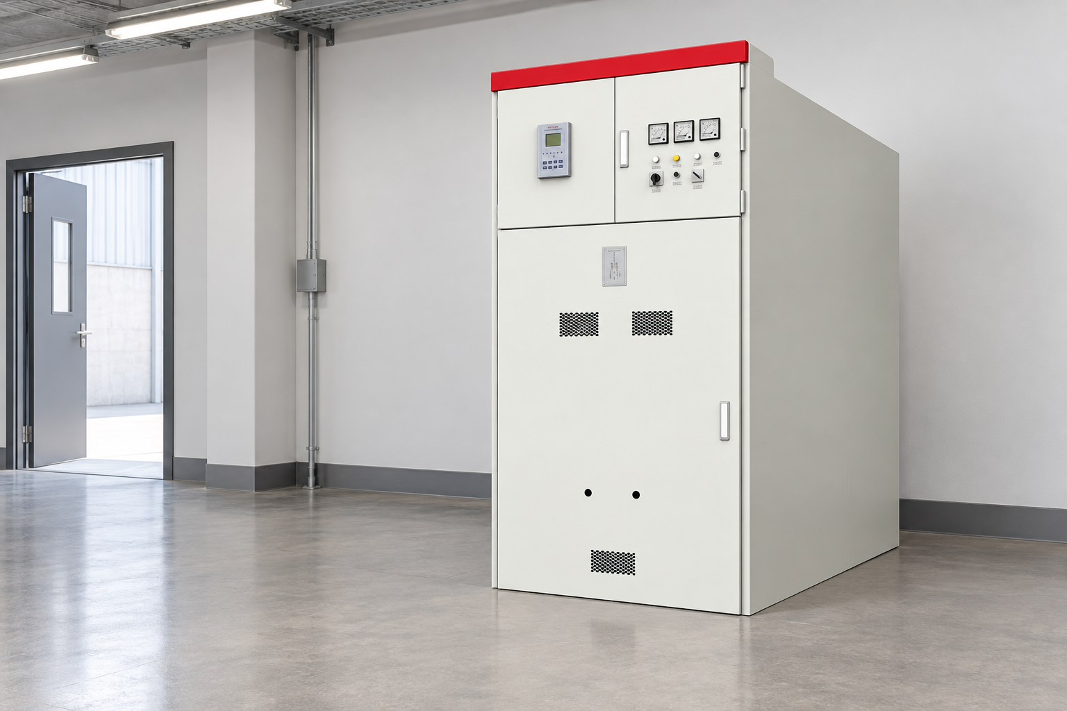
The KYN61-40.5 reference illustrations show a real LBAJI cabinet exterior in uncluttered environments. They communicate equipment form and the importance of access, but they do not establish compliant room dimensions. Request approved drawings and the relevant service envelope for the ordered configuration. At handover, provide the final layout, interface records and room-management requirements to the owner. This turns the floor plan into a usable operating document, while preserving the need for project-specific engineering decisions.
Frequently asked questions
Can a switchgear room be sized from cabinet dimensions alone?
No. Include working access, door movement, component removal, handling arrangements, cable interfaces and the applicable installation requirements.
Are clearances shown in another project suitable for this room?
Not automatically. The equipment, task, voltage class and jurisdiction can differ. Use project-specific criteria and approved supplier drawings.
Why should the delivery route be checked early?
Packed units and handling envelopes may be larger than the bare cabinet. Route constraints need resolution before construction and delivery make changes difficult.
Does empty space guarantee future expansion?
No. Expansion also needs supported equipment interfaces, cable routes, access and an operating strategy. Define the intended future scope rather than reserving only a rectangle.
What should the owner receive at handover?
Provide the final coordinated layout, approved interface information, service envelopes, environmental assumptions and requirements for keeping access routes clear.
Technical sources and related equipment
Standard catalogue pages establish document scope; compliance and acceptance require the applicable full documents and project engineering review.
- IEC 62271-200 metal-enclosed AC switchgear scope
- 29 CFR 1910.333 electrical work practices, official 2025 edition
- LBAJI KYN61-40.5 Armouring Removable AC Metal Enclosed Switchgear
- switchgear equipment fundamentals
- switchgear verification and testing
- switchgear maintenance checklist
Further learning: equipment functions
This independent educational introduction explains the equipment background. It does not demonstrate a safe work procedure for the specific assembly. Source: Gaurav J – TheElectricalGuy.
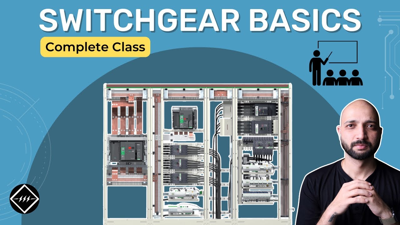
Watch Switchgear Basics: Complete Beginner's Guide | TheElectricalGuy