A switchgear short circuit rating describes a declared fault duty under defined conditions; it is not simply the largest kA number printed on a circuit breaker. Buyers must distinguish the assembly’s withstand capability, the switching device’s making and breaking duties, the applicable voltage and the required fault duration. Those declarations must be compared with a current project fault study using the same definitions and assumptions.
This guide helps procurement and engineering teams organize that comparison. It does not calculate a site’s fault current or authorize equipment operation. An exterior photograph cannot establish a rating. Use the offered assembly documentation, applicable standards and qualified project review to decide whether the equipment is suitable.
Identify the equipment and governing framework
Begin with the assembly boundary. A switchboard, motor control centre and medium-voltage metal-enclosed switchgear lineup may be evaluated under different product standards. A component’s short-circuit declaration cannot automatically be transferred to every assembly containing that component.
Record the governing standard, edition, rated voltage, frequency, assembly configuration and the exact offered revision. IEC 62271-200 addresses metal-enclosed AC switchgear above 1 kV and up to and including 52 kV within its scope. IEC 62271-1 supplies common specifications within its own scope. Other frameworks and equipment classes require their own interpretation.
Avoid casually translating a short-circuit current rating used in one product framework into a medium-voltage breaking or withstand rating used in another. Ask the manufacturer to identify the relevant declarations and how they apply to the complete offered equipment. Where multiple standards are specified, resolve the acceptance basis explicitly.
Distinguish the network duty from equipment capability
The prospective or available fault current is a characteristic of the electrical system at a defined location and operating condition. Equipment ratings describe declared capability under specified conditions. A network study and a catalogue therefore answer different questions, even when both contain values expressed in kA.
The study should identify its fault location, system configuration and calculation assumptions. Source strength, transformer impedance, parallel operation, connected generation and other relevant contributions can influence the result. A minimum-source case may matter for protection sensitivity, while a maximum-source case may govern equipment duty.
IEC 60909-0 provides a calculation framework for short-circuit currents in three-phase AC systems within its scope. A catalogue description of that standard is not the project calculation itself. Obtain the approved study and confirm that its output quantities match the declarations being reviewed.

Understand short-time withstand current
Short-time withstand current addresses the ability to carry a specified fault duty for a stated time under the applicable standard conditions. Both current and duration matter. A declaration without its associated time is incomplete for comparing equipment against a protection clearing requirement.
Ask which current path and assembly construction the value covers. Main bars, connections, earthing circuits and individual functional units may require distinct attention. The manufacturer should explain the relevant assembly declaration and any limitations rather than relying only on a circuit-breaker label.
Do not assume that a shorter protection delay automatically validates equipment with a different declared rating. Any permitted comparison must follow the governing standard and manufacturer evidence, with the project engineer’s approval. A simple current-squared-times-time calculation cannot independently establish mechanical adequacy or all equipment duties.
Understand peak withstand and making duty
A fault waveform can impose significant mechanical stress on conductors and supports. Peak withstand concerns a different quantity from an RMS current rating. A comparison that overlooks the peak duty may leave a material gap even when the short-time RMS values appear satisfactory.
Making duty concerns a switching device closing onto a fault under specified conditions. It should not be confused with a passive assembly’s withstand declaration or with a device’s ability to interrupt current. Ask which rated quantity the supplier is quoting and whether the required voltage and test conditions apply.
Do not introduce an unexplained fixed multiplier to convert every RMS value into a peak value. The appropriate relationship depends on the governing calculation and rating framework. Preserve the study’s definitions and the manufacturer’s declarations so that the reviewer can compare like with like.
Understand breaking duty and operating sequence
Breaking duty concerns interrupting a fault. For circuit breakers, the declared capability applies with specified voltage and other conditions, including the relevant operating sequence and associated requirements. A prominent breaking-current figure alone does not document every duty of the complete installation.
Protection operating time, breaker opening and interruption time contribute to clearing behaviour. Obtain the relevant values and their definitions from the study and device documentation. Do not equate a relay’s programmed time delay with the total time for the fault to be cleared.
Switches, disconnectors and earthing switches do not all perform the same function as a circuit breaker. The single-line diagram, equipment specification and declared device capabilities should identify what each unit is expected to do. Never infer interrupting capability from the appearance of a handle or cabinet door.

Compare the relevant quantities systematically
Reference context: IEC 62271-200 metal-enclosed AC assembly scope. This original qualitative checklist organizes project decisions; it is not a reproduced standard or a substitute for approved criteria.
| Quantity or record | What it describes | Review action |
|---|---|---|
| Prospective fault current | Calculated system duty at a defined location | Obtain the approved study and operating cases |
| Short-time withstand | Declared current carrying duty for a stated duration | Match current, time, current path and construction |
| Peak withstand | Declared peak mechanical duty | Compare with the corresponding study quantity |
| Making capability | Switching device closing duty under stated conditions | Verify the applicable device and rated conditions |
| Breaking capability | Switching device interruption duty | Check voltage, current definition and required operating conditions |
| Assembly evidence | Relationship between declaration and supplied equipment | Confirm drawings, configuration, limitations and revisions |
This qualitative table is not a substitute for the full governing standard. Use it to expose missing definitions before accepting a quotation. The engineering review should record a conclusion for each applicable duty rather than marking a proposal acceptable because one advertised value is high enough.
Review normal and alternative operating cases
A plant can have more than one credible fault case. An open coupler and a closed coupler may produce different source contributions. Emergency generator operation, future transformer additions or permitted parallel supplies can change the study assumptions. Establish which configurations the operating procedures actually allow.
Do not use an interlock as an undocumented reason to ignore a configuration. If a prohibited operating state is essential to the duty assessment, identify the control, its verification and the continuing operating restriction in the accepted documents. The project engineer should approve that boundary.
Future expansion also needs a defined basis. A vague statement that equipment is suitable for expansion does not quantify future fault contribution. Either assess the agreed future arrangement now or state the boundary and the need for reassessment before the system changes.
Request evidence that identifies the offered assembly
Ask for the applicable rating schedule, controlled drawings, verification or test references, device data and technical deviations. The documents should connect to the proposed assembly revision and explain any relevant differences from the verified construction. A test certificate for an unidentified product family has limited decision value.
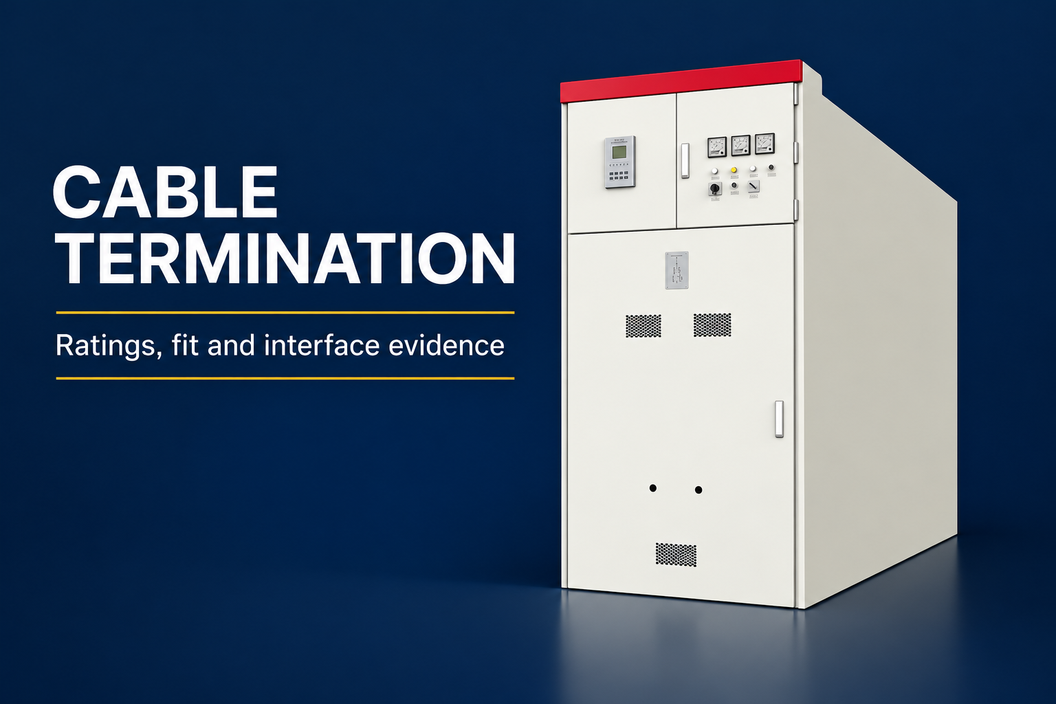
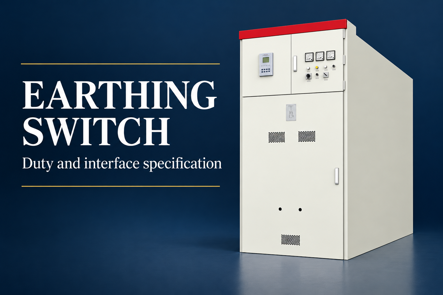
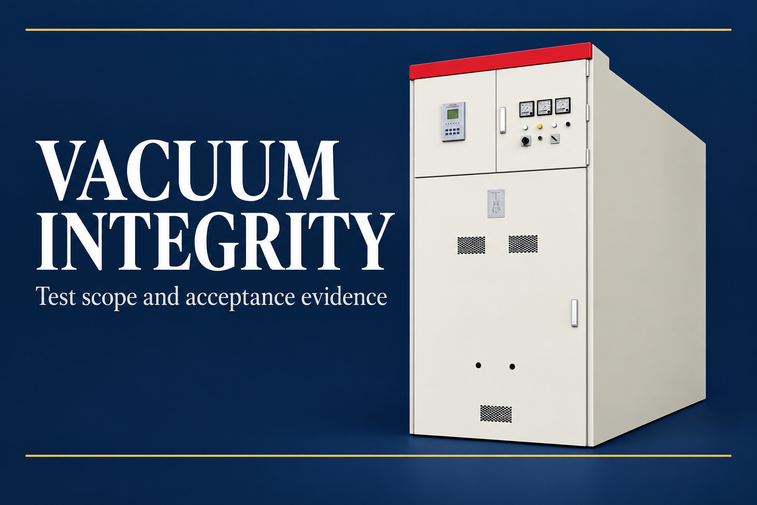
Review joints, supports, conductor arrangement and connected components through the manufacturer’s controlled documents. These details should not be reverse-engineered from a sales photograph. The closed KYN61 illustrations here identify an equipment family only; they do not show a fault test or prove a particular kA rating.
Clarify who will review the evidence and which information is required before manufacture. Commercial acceptance should follow resolution of material duty questions. If a supplier proposes an alternative construction or rating framework, obtain an explicit deviation assessment instead of quietly comparing unlike figures.

Example of a document mismatch
Imagine an offer that advertises a breaker breaking-current value, while the project specification requires a lineup short-time withstand declaration with a stated duration. The numbers may look similar, but the requested assembly evidence is still missing. Ask for the correct declaration and its construction reference.
A second mismatch occurs when the study is based on normal single-source operation but the facility can parallel sources through a coupler. Recalculating the permitted cases may change the required duty. Buying a stronger breaker alone may not address a limitation in bars, supports or another assembly component.
A useful acceptance record states the study revision, applicable cases, compared quantities, equipment document references and unresolved limitations. It allows a later reviewer to understand why the equipment was accepted without reconstructing the whole decision from email fragments.
Preserve the rating basis through installation and service
At delivery, confirm that the equipment identity and supplied documents match the accepted offer. Installation changes, replacement components and additional sources should be reviewed for their effect on the original duty basis. A matching cabinet colour or model family is not sufficient evidence of an equivalent assembly.
After an actual fault, follow the manufacturer’s inspection and return-to-service requirements. A rating is not a promise that every component can remain in service without examination following every event. Record the event conditions and have qualified personnel assess the equipment under an approved safety process.
Keep the accepted fault study, operating restrictions, assembly documents and protection records together. Review them when the network changes. That disciplined link between system duty and equipment evidence is more useful than selecting equipment by the largest isolated short-circuit number.
Frequently asked questions
Is a breaker breaking-current rating the same as an assembly short-time withstand rating?
No. They describe different duties. The relevant switching device and complete assembly declarations must each be reviewed against the corresponding project requirements.
Why is the withstand duration important?
Short-time withstand is declared for a specified duration. The project clearing requirement must be compared using the applicable current and time definitions, rather than treating a kA value alone as complete.
Can I use a fixed multiplier to convert every RMS current into peak current?
No universal multiplier should be assumed. Use the applicable study method and rating framework, preserving their definitions and conditions.
Does the product photograph establish a short-circuit rating?
No. Exterior imagery identifies equipment appearance. Ratings and their applicability require the manufacturer’s controlled declarations and relevant verification evidence.
When should an existing fault-duty assessment be reviewed?
Review it when sources, permitted operating configurations, transformers, generation, protection assumptions or relevant equipment construction change. The approved project engineer should define the reassessment scope.
Technical sources and related equipment
Standard catalogue pages establish document scope; compliance and acceptance require the applicable full documents and project engineering review.
- IEC 62271-200 metal-enclosed AC assembly scope
- IEC 60909-0 short-circuit calculation scope
- UK HSE HSG85: Electricity at work, safe working practices
- LBAJI KYN61-40.5 Armouring Removable AC Metal Enclosed Switchgear
- switchgear equipment fundamentals
- switchgear verification and testing
- factory acceptance witness records
Further learning: technical background
This independent educational video explains the measurement principles or equipment background discussed above. It does not demonstrate a safe work procedure for the specific assembly. Source: Gaurav J – TheElectricalGuy.
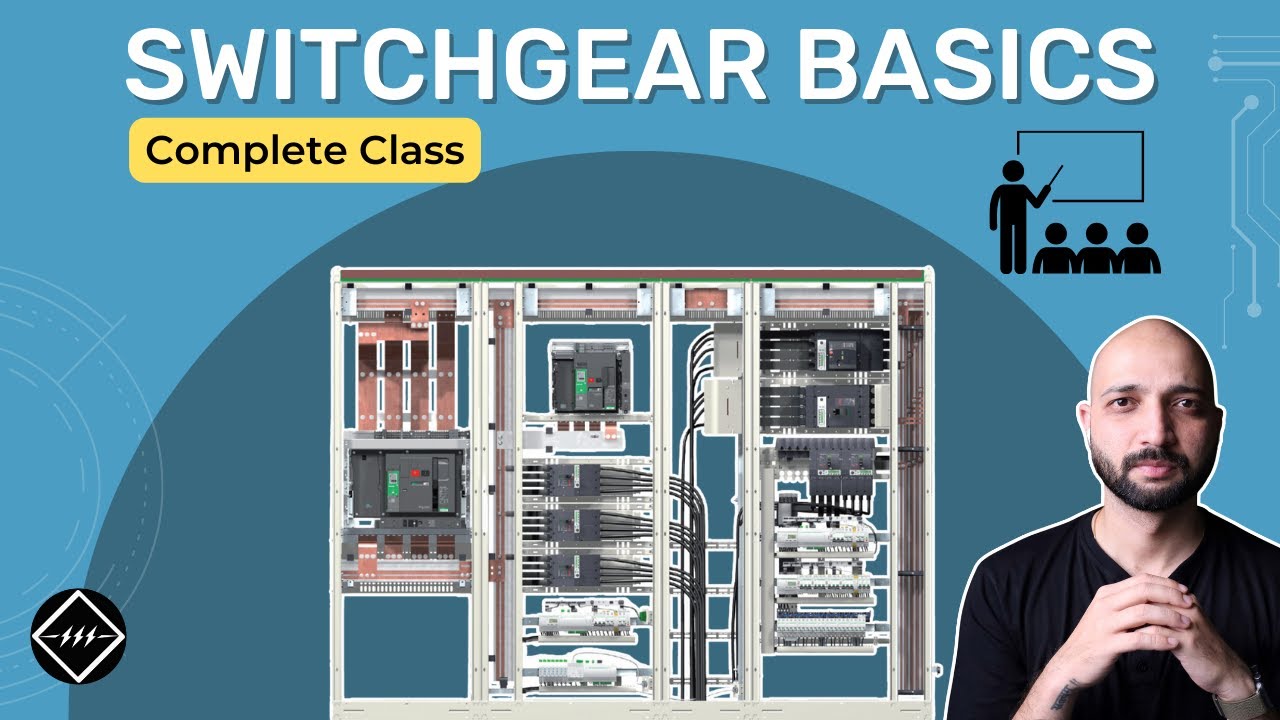
Watch Switchgear Basics: Complete Beginner's Guide | TheElectricalGuy