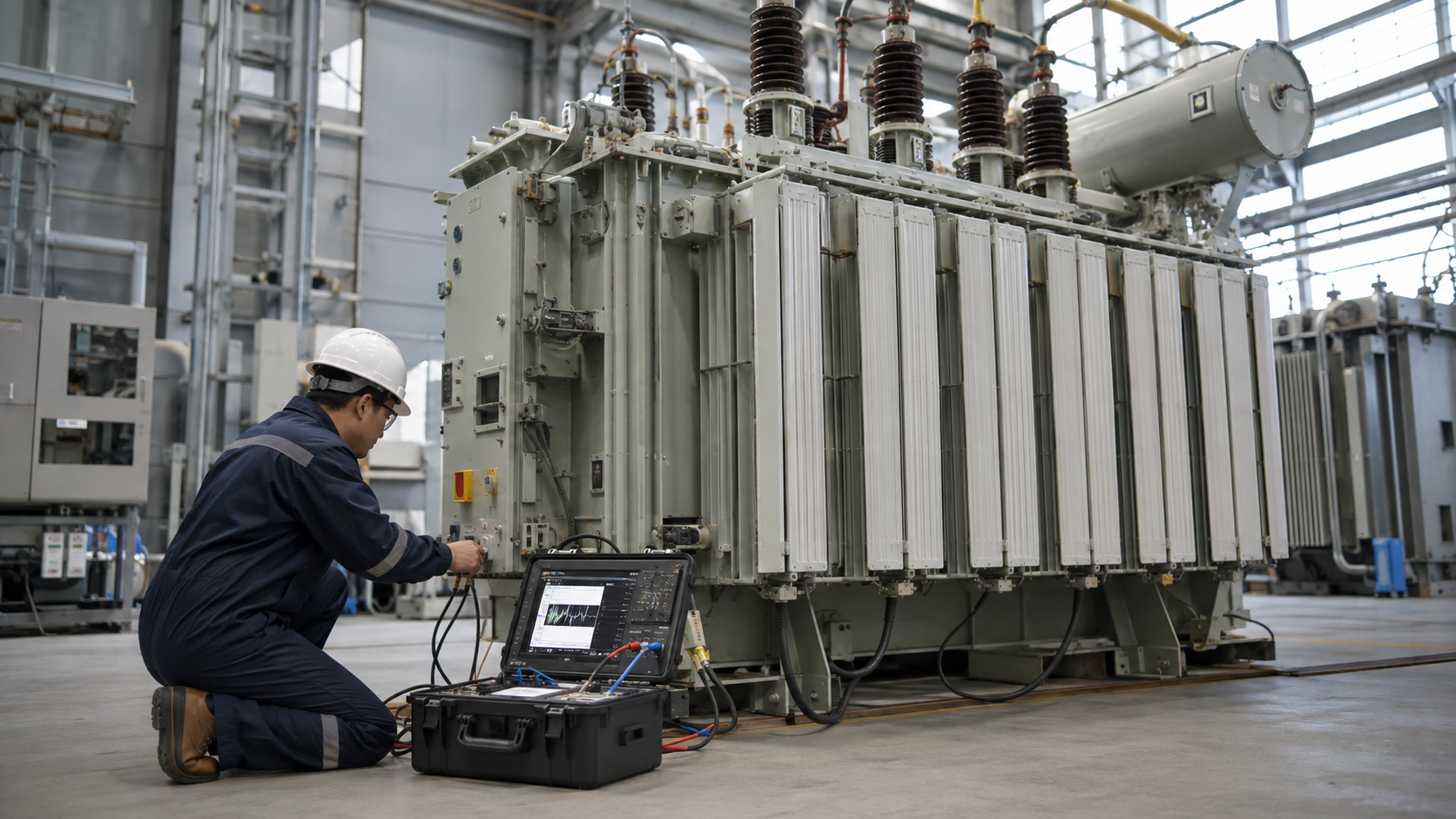
Transformer testing is not one test or one pass/fail number. The right method depends on whether the unit is new, being commissioned, or under investigation after a fault or condition change. This guide compares factory and field test purposes, explains what common measurements can—and cannot—show, and gives a practical report checklist. High-voltage electrical testing must be planned and performed by qualified personnel using the approved equipment and site procedure.
Quick answer: begin with the nameplate, reason for testing, approved test plan and previous results. Common methods include turns ratio, winding resistance and insulation measurements; liquid-filled units may also need oil diagnostics. Interpret related results together against the applicable standard, contract, manufacturer limits and the unit’s own baseline.
Safety and scope come before the test
Transformer test work can expose workers to stored charge, induced voltage, backfeed, arc flash, elevated test voltages, oil hazards and unexpected energization. It is not a do-it-yourself activity. The responsible organization must establish the authorized work boundary and isolation, lockout, verification, grounding, discharge, barriers, personal protective equipment and restoration controls required for that equipment and jurisdiction. The test supervisor should confirm connected cables, secondary circuits, auxiliary supplies, capacitors and parallel sources have been considered.
This article does not provide terminal-by-terminal connections, test-voltage settings, live-probing instructions or a substitute for a switching order. Use the approved manufacturer instructions, site safety rules, governing electrical regulations and test-equipment manual. Testing is complete only after temporary test arrangements are accounted for, the approved connections and protection are restored, and the owner accepts the hand-back record.
Factory, routine, acceptance and field tests are different
Test labels vary across standards and contracts. Agree the governing standard, edition, scope, test schedule and acceptance basis before ordering or mobilizing. An “acceptance test” is a project or owner decision and should not be assumed to mean the same fixed test package for every transformer.
| Stage | Main question | Typical evidence | Who sets acceptance |
|---|---|---|---|
| Factory routine tests | Does this manufactured unit meet its specified design and declared ratings? | Serial-numbered routine-test report and nameplate data; tests depend on unit type and governing standard | Applicable product standard, approved specification and manufacturer criteria |
| Type or special tests | Has a design or requested feature been demonstrated under a defined test program? | Type-test evidence, special-test report or agreed witness record | Contract and the standard clauses agreed for the design |
| Site commissioning / acceptance | Has the delivered installation been checked against the approved drawings and pre-service requirements? | Inspection, configuration records and project-required field measurements | Owner/engineer, contract, utility and local rules |
| Condition / fault investigation | Has the unit changed, and what evidence helps explain an event or trend? | Comparable measurements, event history, oil/lab data and a diagnostic interpretation | Qualified evaluator using manufacturer limits and relevant field-testing guidance |
IEEE C57.12.90 describes test methods for liquid-immersed distribution, power and regulating transformers; it is not a blanket statement that every listed method applies to every product. IEEE C57.152 addresses diagnostic field testing of liquid-filled power transformers and advises interpreting multiple test results together and consulting manufacturer acceptance criteria. The unit, contract and applicable regional rules control.
Choose a test from the question it can answer
Write the concern first: wrong configuration, suspected winding damage, insulation change, oil issue, transport movement or an unexplained protective trip. Then select a method that can discriminate among plausible causes. A broad battery of tests without a decision question can add cost and risk without improving the diagnosis.
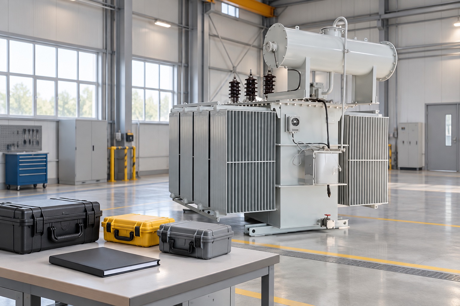
Common transformer tests, instruments and limitations
Test equipment must be suitable for the winding class, measurement range and method. Calibration status, lead arrangement, environmental conditions and the instrument’s own procedure affect whether results can be compared.
| Test or evidence | Typical tool / record | What it can help assess | Important limitation |
|---|---|---|---|
| Turns ratio, polarity and phase relationship | Transformer turns-ratio tester; nameplate, tap and connection drawing | Ratio by phase/tap and whether the configuration agrees with the declared connection | A ratio result must be interpreted with the selected tap, winding connection and instrument method; line ratio is not always the simple winding ratio |
| Winding resistance | Suitable low-resistance ohmmeter or winding-resistance instrument; winding temperature | Possible contact, joint, tap-changer or conductor changes when compared phase-to-phase and with a baseline | Temperature, lead/contact resistance, stabilization and residual magnetism matter; one low value does not prove a shorted turn |
| Insulation resistance / polarization response | Insulation resistance tester selected for the equipment; temperature, humidity and test-duration record | Comparative insulation condition under a specified test setup | No universal megohm value proves health; moisture, contamination, temperature and connected accessories can alter results |
| Dielectric loss / capacitance | Power-factor or dissipation-factor test set; winding/bushing configuration and environmental conditions | Changes in insulation-system or bushing condition when validly compared | Requires controlled setup and interpretation; a single number is not a complete diagnosis |
| Oil quality and dissolved gases | Qualified laboratory sample; oil identity, sampling point, load and event history | Liquid properties and possible thermal/electrical activity in oil-filled equipment | Sampling, recent oil processing and trends affect meaning; DGA is not an oil test for a dry-type transformer |
| Excitation, loss, impedance or dielectric withstand | Factory test system or specialized field equipment under an approved plan | Specified performance or a targeted investigation of electrical condition | Test energy and consequence can be significant; applicability, limits and qualified oversight are essential |
| Frequency response / leakage reactance | Frequency-response analyzer or appropriate impedance measurement system | Comparative evidence of winding/core geometry changes after a credible mechanical event | Test connections and baseline comparison are critical; it is not a stand-alone verdict |
High-level field sequence and decision gates
- Define the purpose. Record whether the work is commissioning, routine trending, a post-fault investigation or an inspection after transport or repair.
- Confirm equipment identity. Capture serial number, nameplate, winding connection, tap, accessories, oil/dry-type construction and approved drawings.
- Approve the test plan and safety controls. Assign qualified personnel, equipment, isolation boundaries, grounds and restoration responsibilities under site rules.
- Inspect and collect context. Review visible condition, alarms, relay/event records, operating load, temperatures, recent maintenance and previous test results.
- Use the specified method. Record the instrument, calibration status, connection, settings required by the approved method and environmental conditions; do not improvise a setup.
- Compare on a valid basis. Compare with nameplate/factory data, other phases, prior readings and the applicable standard or contract, correcting only as the approved method requires.
- Resolve anomalies before release. Check configuration and test quality first, then select complementary diagnostics. Escalate uncertain or unsafe results to the responsible engineer/manufacturer.
- Restore and hand back. Independently confirm test leads and grounds are dealt with, accessories and protection restored, work permits closed and the service recommendation documented.
This is a planning framework, not the operating sequence for a particular transformer. The approved work package and safe switching procedure remain controlling.
What counts as an acceptable result?
There is no single acceptance threshold that applies to all transformer sizes, designs, insulation systems, test voltages, temperatures and jurisdictions. Start with the purchase specification and manufacturer’s guaranteed data, then use the standard edition referenced by the contract. For an in-service unit, compare like-for-like readings with its commissioning baseline and earlier trend, accounting for test setup and environmental changes.
For example, a winding-resistance difference may warrant a setup, temperature, tap or contact check before it is called a defect. An insulation reading should include how, when and under what conditions it was obtained; a higher number alone does not rule out every failure mode. A changed oil-gas pattern should be evaluated with gas generation rate, load, temperature, prior oil work and other test evidence. State the acceptance basis and uncertainty beside every conclusion. Do not transplant a limit from another transformer model or an unverified online chart.
IEC 60076-1 sets general requirements for power transformers within its scope. The official IEEE pages for C57.12.90-2021 and C57.152-2025 describe factory test methods for liquid-immersed units and diagnostic field-testing guidance respectively. Confirm current editions and the exact scope that applies to the project; standards are not substitutes for the complete purchased documents or manufacturer limits.
Transformer test report checklist
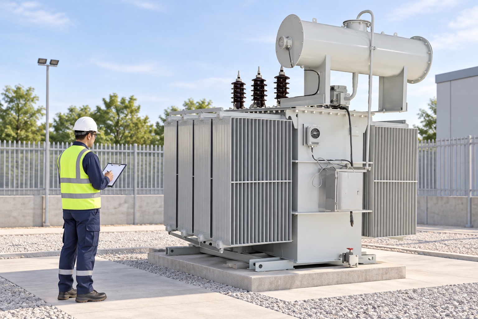
A report should let another engineer reproduce the comparison and understand why the service decision was made. Use this as a record outline and adapt it to the approved contract and site form.
| Report field | Record to retain |
|---|---|
| Equipment | Owner/site, manufacturer, model, serial number, rated kVA, primary/secondary voltage, phase, frequency and connection |
| Configuration | Actual tap, terminal/connection arrangement, accessories, status of connected components and approved drawing revision |
| Purpose and authority | Commissioning/routine/fault/repair reason, work authorization, test-plan reference, applicable standard and acceptance basis |
| Conditions and instruments | Date/time, ambient and winding/oil temperature as available, humidity where relevant, instrument make/model/serial, calibration date and method |
| Measurements | Raw values and units by phase/tap, test arrangement and duration, corrections applied, factory/previous comparison and missing data |
| Findings and disposition | Observed facts separate from interpretation; limitations, follow-up tests, repair recommendation, return-to-service authorization and responsible sign-off |
Prepare the factory test and witness plan
Before a factory test or owner witness point, agree the drawing and specification revisions, transformer serial number and test schedule. The purchase document should state the required standard and edition, routine-test deliverables, any type or special tests, data format, witness/hold points, acceptable deviations and who approves release for shipment. Confirm that the offered design is the one being tested; an old type-test report for a different rating or construction may not answer the contract requirement.
During review, check the unit identity and configuration first, then match each required test line to its report page and acceptance basis. Record actual measured values, units, phase/tap, correction or reference conditions and instrument identification as supplied. Resolve missing data, unexplained deviations or pending accessories in writing before shipment. A witness signature confirms the defined observation occurred; it is not a substitute for the responsible engineer’s review of results.
Factory reports do not automatically replace site commissioning. Transport, storage, installation, cable connections, protection settings and local acceptance requirements introduce separate checks. Keep the factory report available as the starting baseline for field comparison, and identify any pre-energization tests required by the owner, utility and project specification.
Three examples of combining evidence
- Commissioning discrepancy: a ratio differs from the scheduled value. First confirm unit serial number, tap, connection drawing and tester configuration; compare each phase with the factory report before attributing it to winding damage.
- After a protection trip: read the relay/event evidence and correlate it with the fault location, loading and inspection. A cable-side fault can trip protection without proving an internal transformer defect, while no visible leak does not rule out internal damage. Choose tests to resolve the specific concern.
- Condition trend: insulation or oil results have changed. Check whether test conditions, sampling and operating history are comparable, then review the trend alongside other relevant evidence. Escalate material changes using the owner’s engineering process rather than relying on one isolated reading.
Related maintenance and equipment guidance
Testing should connect to a wider maintenance decision: see the transformer maintenance checklist, DGA trend interpretation guide, and transformer protection and safety guide. For the limits of basic checks, read how to test a transformer using a multimeter; that page also does not authorize high-voltage work. The transformer fundamentals guide and connection-diagram guide cover related theory and drawings. For a product example, review the 35 kV oil-immersed transformer page and confirm exact specifications with the approved data sheet. For field work planning, see the substation maintenance guide.
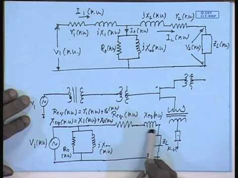
Watch: classroom transformer testing fundamentals
This NPTEL IIT Kharagpur lecture covers testing of a single-phase transformer in an educational context. It is useful for understanding basic laboratory measurements, but it is not a field-testing procedure for distribution or power transformers.
Frequently asked questions
What is the most important transformer test?
It depends on the question. Ratio and winding checks can verify configuration or identify changes; insulation, oil and specialized diagnostic tests address other failure modes. No single test proves overall health, so interpret relevant evidence together.
Can I test a transformer with a multimeter?
A multimeter can support limited checks on a properly isolated low-voltage transformer, but it cannot establish insulation strength or rated-load condition. Do not probe energized utility or high-voltage terminals; use qualified personnel and an approved method.
What are the acceptance limits for transformer tests?
Limits depend on transformer design, test method, standard edition, contract and manufacturer data. Compare like-for-like measurements with the factory report and historical baseline; do not use a generic online number as a universal pass/fail rule.
Are factory tests and field tests the same?
No. Factory routine tests document the manufactured unit under the applicable product standard and purchase specification. Field commissioning and diagnostic tests address installation or condition questions and use their own approved acceptance basis.
What information belongs in a transformer test report?
Include unit identity and ratings, connection and tap, reason and approved standard, test conditions, instruments and calibration, raw readings by phase, corrections, comparison basis, findings, limitations, follow-up and return-to-service sign-off.
Conclusion
A useful transformer test program begins with a decision question, follows an approved and safe plan, and ends with comparable data and a documented disposition. Separate factory compliance from site acceptance and in-service diagnostics; use the right test for the suspected condition, and let the applicable standard, manufacturer and project criteria—not a generic number—define acceptance.