A circuit breaker timing test records when specified contacts change state in relation to an opening or closing command. Combined with suitable travel measurements and control-circuit records, it helps engineers assess whether a mechanism operates consistently and within its approved criteria. It does not measure fault-clearing capability by itself. For a medium-voltage switchgear project, the most useful output is a traceable set of timing curves, operating conditions and engineering decisions linked to the actual breaker, rather than a single unexplained operating-time figure.
Define the timing quantity before discussing limits
Opening time, closing time, pole discrepancy and a complete operating sequence describe different events. A test report should define the command reference and the contact event used for each quantity. Without those definitions, two reports can appear inconsistent even when they describe the same operation using different measurement boundaries.
Ask whether the record concerns main contacts, auxiliary contacts or another signal. An auxiliary contact indicates a mechanism-related state but should not automatically be treated as an exact substitute for the main contact transition. Likewise, the time from a protection relay detecting a fault to current interruption includes several processes beyond a mechanical no-load timing test.
Identify the supplied breaker and mechanism
Record the breaker model, serial number, mechanism type, rated auxiliary supply and applicable drawing revision. Identify the exact test procedure and the manufacturer’s acceptance requirements. Similar-looking switchgear fronts may contain different breaker mechanisms or control arrangements, so an exterior photograph cannot establish the correct timing limit.
For a withdrawable assembly, also state the breaker position and how its control circuit is connected for the approved test. A disconnected breaker test and a complete installed control-chain test answer different questions. Both can be useful, provided the report makes their boundaries explicit and avoids claiming that one automatically proves the other.
Establish a safe and controlled test boundary
Timing tests involve deliberate mechanical operations and may use stored energy or external auxiliary supplies. Qualified personnel must work under the relevant isolation, access and equipment instructions. The work plan must address the primary circuit, auxiliary circuits, stored-energy mechanisms and any temporary test connections. A test instrument does not establish that the assembly is safe to access.
Agree who can issue commands and who controls the test area. Remote commands, automatic schemes and unexpected restoration of an auxiliary supply need consideration in the authorized procedure. This guide focuses on specifying and interpreting evidence; it does not provide a connection sequence or permission to operate equipment outside its instructions.
Record the auxiliary supply at the relevant boundary
A nameplate control voltage is not the same as the voltage available at a coil during an operation. Supply behavior, cable resistance and the test arrangement can influence the observed response. Record the supply conditions required by the approved procedure, including the measurement boundary and whether the test uses the installed supply or an external source.
When comparing results, verify that the operating conditions are comparable. A changed battery condition or a different temporary supply can make a time difference difficult to interpret. Do not adjust the supply until a desired result appears without preserving the original conditions and obtaining engineering direction. The record should explain each changed condition and its purpose.
Separate contact timing from mechanical travel
A contact timing channel reports an electrical transition at the instrument’s defined threshold. A travel transducer records motion at its mounting point. Translating that motion into contact travel may require a manufacturer-approved linkage relationship or geometry. Incorrect mounting can produce a plausible-looking curve that does not represent the intended quantity.
A complete travel assessment may consider stroke, velocity, overtravel, rebound or other manufacturer-defined features. The applicable definitions and evaluation intervals matter. Avoid comparing a velocity value calculated over one portion of the stroke with a limit defined over another portion. Retain the raw curve and analysis settings so the interpretation can be reviewed.
Contenu de référence : IEC 62271-100 alternating-current circuit-breaker scope. Cette liste de contrôle qualitative originale organise les décisions relatives aux projets ; elle ne constitue pas une norme reproduite ni un substitut des critères approuvés.
| Preuve | Question it answers | Important boundary |
|---|---|---|
| Main contact timing | When did each measured pole change state? | Defined command reference and instrument threshold |
| Auxiliary contact timing | When did a selected control contact change state? | Identified contact and its relationship to mechanism position |
| Travel curve | How did the measured mechanism point move? | Approved transducer mounting and conversion method |
| Coil current trace | How did the operating circuit respond? | Instrument setup and synchronized time reference |
| Sequence record | Did the specified operations occur in order? | Agreed operation sequence and recovery conditions |
| Acceptance review | Are the results suitable for this breaker? | Applicable manufacturer and project criteria |
Interpret pole discrepancy with suitable criteria
Differences between the measured pole transitions can be relevant to a three-phase breaker assessment. The report should identify which transitions were compared, the operating direction and the calculation method. A maximum-minus-minimum value is useful only when the underlying events and reference points are understood.
Do not invent a universal allowable discrepancy for all medium-voltage breakers. The appropriate basis depends on the supplied design, specified standard and manufacturer requirements. If a phase differs from its baseline, review the setup and trace quality before attributing the change to the mechanism. Persistent differences require an engineering decision and a documented follow-up action.
Specify the operating sequence explicitly
A simple open or close operation does not cover every possible duty. A project may require evidence for an agreed sequence, particular auxiliary supply conditions or interaction with a control scheme. Define those requirements in the test schedule and distinguish them from the equipment’s rated making and breaking duties.
A no-load mechanical sequence must not be described as a short-circuit interruption test. Similarly, a successful local command does not prove that a remote protection trip path operates correctly. The acceptance package should show which functions were actually exercised and which require separate functional or commissioning checks. This avoids broad claims based on a narrow measurement.
Compare curves without discarding the original data
A factory curve can provide a useful baseline for site and maintenance assessments. Preserve the original instrument files where available, together with exported plots, channel assignments and settings. A screenshot alone may omit the time scale, trigger definition or information needed to calculate a result consistently.
When conditions differ, explain the difference before drawing a trend conclusion. Mechanism condition, elapsed storage, preceding operations and authorized maintenance can affect comparability. If the test is repeated, retain both runs and identify any setup correction. Deleting an initial outlier can remove the evidence needed to understand the equipment’s behavior.
Investigate unusual timing as a system issue
An unexpected trace can originate in the test arrangement, the control circuit or the breaker mechanism. Begin with the validity of the measurement: channel identity, trigger, connections, transducer behavior and operating conditions. Then use the manufacturer’s troubleshooting process and the site’s authorized work controls to investigate a persistent deviation.
Do not lubricate, adjust or replace mechanism parts solely on the basis of an unexplained timing value. Maintenance materials, adjustment procedures and replacement parts must be approved for the supplied design. After authorized corrective work, document the intervention and repeat the specified checks. A lower time is not automatically a better result if other criteria are no longer satisfied.
Put useful timing requirements into procurement documents
A buyer can request a defined factory test report, raw curve availability, instrument identification and an explicit list of measured channels. Agree witness points and the treatment of deviations before the test. Specify the applicable standard edition and require the supplier to identify the model-specific acceptance criteria rather than relying on an undated generic checklist.
For an LBAJI KYN61 project, the assembly product page provides equipment-family context. The actual breaker designation, mechanism, control voltage and test boundaries must come from the project documents. Require a clear relationship between the delivered breaker serial numbers and the reports. If replacement breakers are supplied later, update the baseline and compatibility records accordingly.
Connect timing results to commissioning and maintenance
During commissioning, timing evidence should be reviewed alongside mechanical operation, interlocking, primary circuit verification, protection and control checks. The complete readiness decision belongs to the approved commissioning process. A timing report cannot close unrelated insulation, safety or documentation issues, even if every recorded value falls within its individual criterion.
For maintenance planning, use the manufacturer’s recommendations, service history, actual operating duty and the site’s risk assessment. A trend may justify closer investigation, but this article does not establish a universal maintenance interval. The maintenance record should identify the next action, responsible reviewer and any operating restriction so that the test result leads to a clear decision.
Close the report with an assessment and limitations
A useful final report states what was tested, what was excluded, which criteria were applied and whether any result remains unresolved. Link the conclusion to the raw records and equipment identity. If an auxiliary channel was unavailable or a curve could not be interpreted, disclose the limitation instead of silently marking the whole package satisfactory.
Complete restoration under the approved procedure, including removal of temporary connections and confirmation of required final states. Handover must identify any pending work. This makes the timing test a reliable part of the equipment history and allows a later team to understand both the measured performance and the practical limits of the conclusion.
Foire aux questions
What is a circuit breaker timing test?
It records defined contact transitions relative to an operating command. The report must identify the measured contacts, time reference, operating conditions and applicable criteria.
Does opening time equal total fault-clearing time?
Not necessarily. Protection operation, control circuits, mechanism motion and current interruption contribute different parts of the complete event. A mechanical timing test has a narrower boundary.
Can auxiliary contact timing replace main contact timing?
Only where the approved method establishes the relationship needed for the assessment. An auxiliary contact should not automatically be treated as an exact main contact indication.
Why retain travel curves and raw instrument files?
They preserve the channel assignments, time scale and analysis settings needed to review the interpretation. A single summary number or cropped plot may omit important evidence.
Can the same time limit be used for every breaker?
No. Apply the supplied model’s manufacturer criteria and the agreed project requirements under the specified conditions. Similar exterior dimensions do not establish equivalent operating characteristics.
Sources techniques et équipements connexes
Les pages du catalogue standard définissent le champ d’application du document ; la conformité et l’acceptation requièrent la consultation des documents complets applicables ainsi que l’examen de l’ingénierie du projet.
- IEC 62271-100 alternating-current circuit-breaker scope
- NPTEL Power System Analysis: circuit breaker operating time and selection
- UK HSE HSG85: Electricity at work, safe working practices
- LBAJI KYN61-40.5 Armature de commutation en métal amovible avec prise électrique
- Fondements de l'équipement de distribution électrique
- vérification et essais des équipements de commande
- switchgear thermal inspection evidence
Formation continue : formation technique
Cette vidéo éducative indépendante explique les principes de mesure ou le contexte technique évoqué ci-dessus. Elle ne démontre pas une procédure de travail sécuritaire pour le montage spécifique. Source : Gaurav J – TheElectricalGuy.
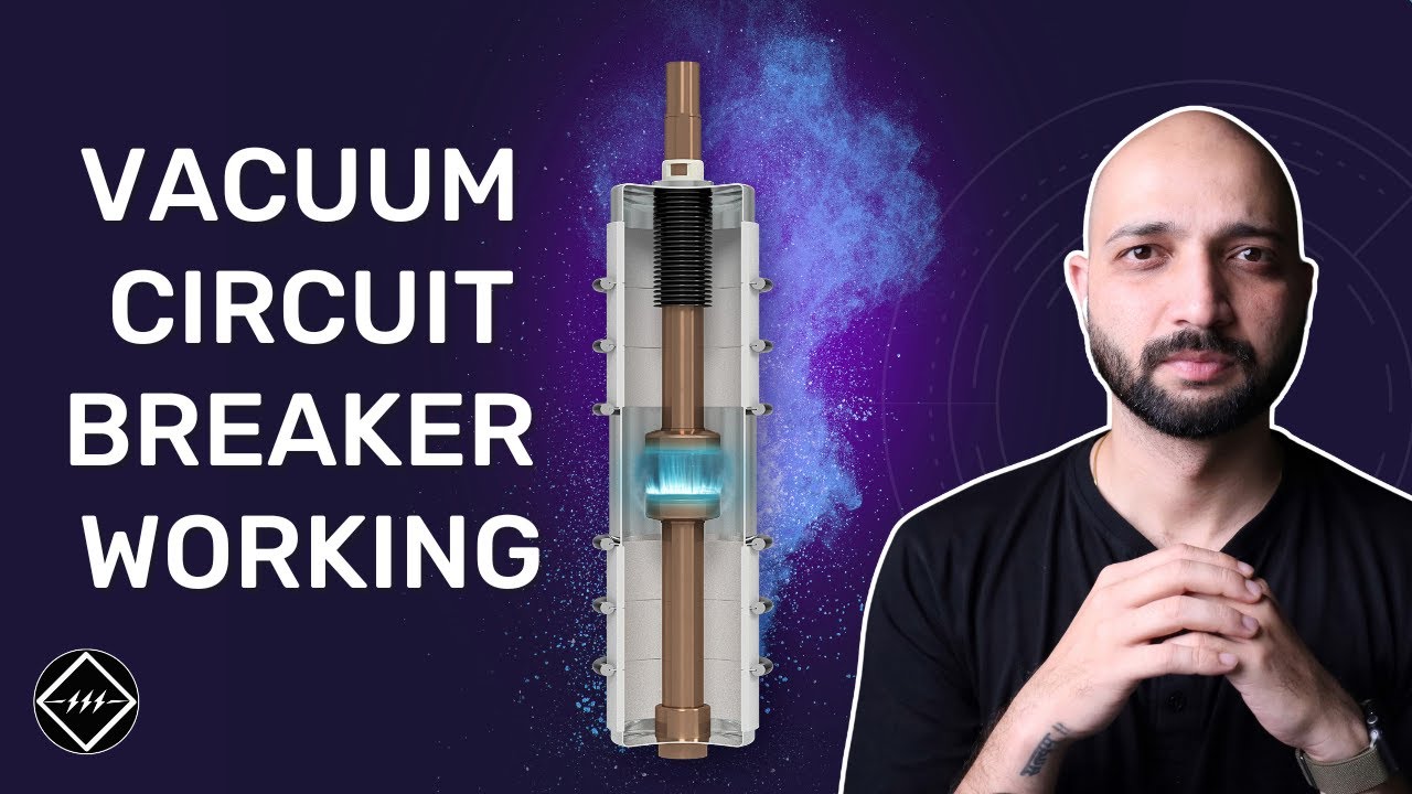
Watch Working Principle of Vacuum Circuit Breaker | Step by Step Explained | TheElectricalGuy