A switchgear earthing switch connects a defined part of the primary circuit to earth when operated under its approved conditions. Specifying it requires more than selecting an operating handle: the project must establish the circuit being earthed, applicable duties, interlocks, position indications and evidence for the supplied arrangement. It is a different subject from the enclosure’s protective bonding network. For a medium-voltage procurement package, a useful specification connects the device’s documented capability to a clear operating-state matrix and the site’s authorized safety procedures.
Distinguish the earthing switch from protective bonding
Protective bonding connects conductive parts such as enclosures to the intended protective earthing system. An earthing switch is a switching device associated with a defined primary circuit. These functions interact in the complete installation, but they do not have the same specification or verification boundary.
A drawing should identify the earthing switch location, the primary conductors it connects and the associated earth path. Do not infer this arrangement from a visible earth bar or cabinet label. For a multi-compartment assembly, establish whether the device earths a cable circuit, another circuit section or a particular configuration. The precise scope belongs in the single-line and arrangement documents.
Begin with the operating purpose
Ask what work or operating state the earthing switch is intended to support and who controls that state. The answer must be compatible with the assembly design and the site’s safety rules. An earthing switch can be part of a controlled safety arrangement, but its presence does not by itself prove the absence of voltage or establish permission to access equipment.
Potential sources can include the normal supply, another feeder, a connected generator or other project-specific paths. The responsible engineer must review the actual system. A simple radial diagram used for discussion must not be assumed to represent a more complex installation. Record the agreed operating boundary and relevant alternative supply conditions.
Specify duties using the applicable equipment documentation
An earthing switch has defined characteristics that must be suitable for its application. The applicable standard family and supplied manufacturer’s data establish which duties and classifications are relevant. A buyer should request the declared ratings and evidence rather than treating every device as equivalent because it fits within the same cabinet.
Do not assume that an earthing switch is intended to interrupt load current. Similarly, short-circuit making capability and short-time withstand describe different aspects of duty. The project specification should identify the required characteristics and have the supplier confirm the complete arrangement. A broad assembly fault rating is not enough to explain every component’s individual duty.
Review the actual circuit diagram
Use the single-line diagram to locate the earthing switch electrically and the arrangement drawing to understand its physical relationship with compartments and access points. Confirm the delivered configuration against both. An optional device shown in a catalogue should not be assumed to be included in an order unless the project documents establish that scope.
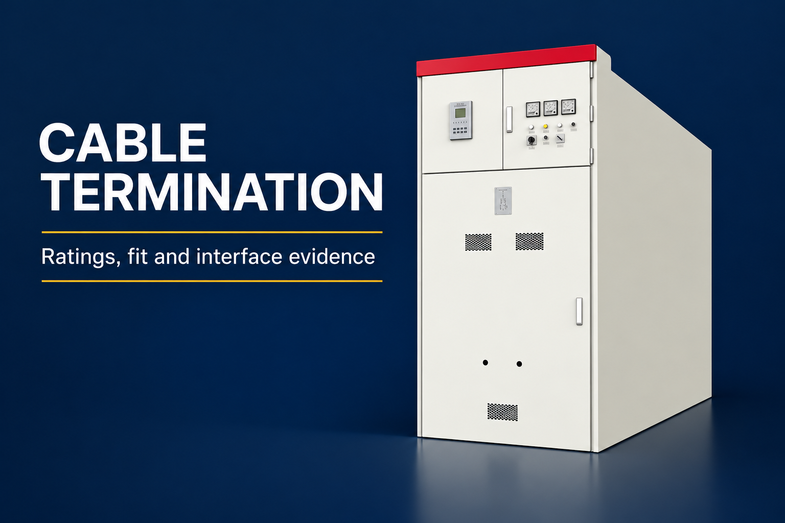
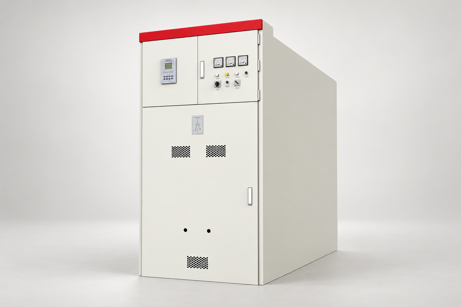
For an LBAJI KYN61 assembly, the product page provides the equipment-family reference. It does not establish the exact earthing switch model, location or ratings for a particular project. Request those details through the offered configuration, drawings and supporting test documentation. This prevents an enclosure photograph from becoming an unsupported statement about internal equipment.
Build an operating-state matrix
A useful matrix states the permitted and prevented actions for each relevant equipment state. Depending on the actual design, the review may need to consider breaker position, primary switching state, earthing switch state, compartment access and key or electrical control conditions. The supplier should explain the implemented logic and any project-specific options.
Keep the matrix precise enough to verify. A phrase such as ‘complete safety interlocking’ does not tell a witness which action should be prevented under a defined state. Record the required action, prerequisite state, expected response and verification evidence. Resolve exceptions before acceptance rather than relying on an operator to discover them after delivery.
Contenu de référence : IEC 62271-102 disconnectors and earthing switches scope. Cette liste de contrôle qualitative originale organise les décisions relatives aux projets ; elle ne constitue pas une norme reproduite ni un substitut des critères approuvés.
| Specification item | Question à résoudre | Documents à demander |
|---|---|---|
| Electrical location | Which conductors are connected to earth? | Single-line diagram and earthing arrangement |
| Declared duty | Which ratings and classifications apply? | Device data and applicable verification records |
| Permitted operations | Under what states may the switch operate? | Approved operating-state matrix |
| Position indication | How is the actual position established? | Manufacturer indication and verification description |
| Access relationship | What access is permitted or prevented? | Compartment and interlock drawings |
| Control interfaces | Are keys or electrical conditions involved? | Key schedule and control-circuit documents |
| Passation | What restrictions and procedures apply? | Operating instructions and deviation closure |

Check interlock interfaces without bypassing them
Mechanical, electrical and key-based interlocks can enforce different parts of an operating sequence. A complete review identifies which mechanism performs each function and which information it relies on. An interlock that uses an auxiliary signal has a different boundary from a direct mechanical restriction, and that distinction should be documented.
Verification must follow the supplied instructions and an authorized test plan. Do not defeat an interlock to demonstrate a sequence or treat resistance to operation as an invitation to use more force. If the expected action is not possible, stop and investigate the equipment state and instructions. The report should preserve the observed condition and the resulting decision.
Evaluate position indication carefully
A handle position, mimic indication, auxiliary contact and direct view of a mechanism do not necessarily provide identical evidence. The manufacturer’s documentation should explain what each indication represents and how the relevant state is verified. Use that explanation to define the project acceptance checks.
Where remote indications are required, identify the signals and their destination in the control system. A correct local indication does not prove that the remote label or alarm is correct. Functional checks should establish channel identity, polarity where relevant and expected state behavior. Record any limitations so operators understand which indications can support the approved operating procedure.
Consider interfaces with cables and other equipment
The circuit associated with an earthing switch may extend beyond the assembly. Cable connections, alternative supplies and adjacent equipment can affect the operating boundary. Coordinate those interfaces through the project drawings and site work controls. Do not assume that the switch’s local location describes the complete electrical zone involved.
The supplier and purchaser should agree responsibility for information about the external system. This includes any special operating conditions, key exchanges or remote control dependencies. A factory inspection can verify the supplied assembly within its test boundary, while site commissioning must verify the completed interfaces. Record both scopes rather than treating a factory report as proof of the whole installation.

Request applicable verification evidence
Ask the supplier to identify the test or design evidence supporting the declared device and assembly characteristics. The report must be applicable to the supplied configuration, with any differences explained. A certificate for another mechanism or arrangement requires a documented applicability review; a shared manufacturer name is not sufficient.
Distinguish qualification evidence from routine project checks. The purchaser may review applicable design reports while witnessing an operating or interlock check on the delivered assembly. These activities answer different questions. Avoid asking a routine factory operation to demonstrate a fault-duty characteristic that requires a different kind of verification.
Plan maintenance around the supplied design
The manufacturer’s instructions should define inspection, servicing and replacement requirements. The maintenance plan should account for the actual operating duty, environment, service history and the site’s risk assessment. This article does not establish a universal number of operations or inspection interval.
Record abnormal effort, damaged indications, inconsistent interlocks or other observed changes for engineering assessment. Do not adjust linkages, substitute keys or apply unapproved lubricants to obtain a preferred feel. After authorized maintenance, complete the specified functional checks and update the records. The purpose is to preserve the designed relationships among mechanism, indication and access control.
Make the procurement question set concrete
Before approving a quotation, confirm the electrical location, declared duties, operating arrangement, interlock matrix, local and remote indication, applicable reports and included instructions. Identify any optional features explicitly. Agree the witness scope and treatment of deviations so that the delivery package can be checked against a clear requirement.
If the supplier proposes a substitute device, review more than dimensions. Ratings, interfaces, indication behavior and supporting verification may differ. Update the drawings and operating documents after an accepted change. The operator should receive a consistent set of information describing the equipment actually delivered, rather than a mixture of original and replacement configurations.
Handover with clear operating boundaries
Commissioning should establish that the completed installation matches the approved drawings and the agreed functional requirements. The final record should include test results, interlock findings, indication checks and outstanding restrictions. An unresolved discrepancy should remain visible until the responsible engineer closes it.
Operating instructions must work with the site’s electrical safety process. An earthing switch is one component of that controlled system and should never be presented as a substitute for authorization, isolation and verification. Clear documentation helps users understand the device’s purpose while preventing an equipment feature from being mistaken for a complete safety decision.
Foire aux questions
What does a switchgear earthing switch do?
It connects a defined primary circuit section to earth under its approved operating conditions. The exact electrical boundary must be established by the supplied drawings and instructions.
Is it the same as the cabinet earth bar?
No. The enclosure’s protective bonding network and a primary-circuit earthing switch have different functions and verification boundaries, even though they form parts of the same installation.
Can an earthing switch interrupt normal load current?
Do not assume so. Confirm the actual device duties and permitted operations using its declared characteristics and the approved operating instructions.
Does a closed earthing switch alone authorize access?
No. Access requires the site’s complete authorized safety procedure and the relevant equipment conditions. Position indication and interlocks support defined functions within that process.
What should a buyer request before acceptance?
Request the circuit location, declared ratings, applicable verification, operating-state matrix, indication details, interface drawings, instructions and closure of any deviations.
Sources techniques et équipements connexes
Les pages du catalogue standard définissent le champ d’application du document ; la conformité et l’acceptation requièrent la consultation des documents complets applicables ainsi que l’examen de l’ingénierie du projet.
- IEC 62271-102 disconnectors and earthing switches scope
- Scénario de l'IEC 62271-200 pour les équipements de commutation à courant alternatif à protection métallique
- UK HSE HSG85: Electricity at work, safe working practices
- LBAJI KYN61-40.5 Armature de commutation en métal amovible avec prise électrique
- Fondements de l'équipement de distribution électrique
- vérification et essais des équipements de commande
- switchgear thermal inspection evidence
Formation continue : formation technique
Cette vidéo éducative indépendante explique les principes de mesure ou le contexte technique évoqué ci-dessus. Elle ne démontre pas une procédure de travail sécuritaire pour le montage spécifique. Source : Gaurav J – TheElectricalGuy.