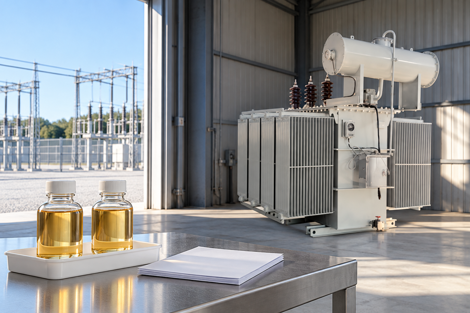
Transformer sweep frequency response analysis, usually called SFRA, compares a transformer’s electrical frequency-response signature with a suitable reference to investigate possible changes in its winding and core assembly. It is especially useful when reviewing transport damage or a significant through-fault. A different trace is evidence to investigate, not a standalone diagnosis or permission to energize. The practical question is whether the comparison represents the same transformer, configuration and measurement conditions. A useful report preserves the original traces, documents the setup and explains how the findings agree with other inspection and test evidence.
What the frequency-response signature represents
A transformer contains distributed inductance, capacitance and resistance. These properties depend partly on the arrangement of windings, leads, insulation and magnetic structure. A frequency-response measurement examines how an applied signal transfers between defined terminals across a specified frequency range. Resonances and changes in attenuation create a recognizable signature. Mechanical movement can change that signature, but so can a measurement arrangement that differs from the original test.
This makes SFRA a comparative diagnostic method. It does not photograph an internal defect, directly measure insulation strength or calculate remaining operating life. Its value comes from disciplined comparison. A trace with sharp features is not automatically defective; healthy equipment also has resonances. Likewise, smooth-looking traces do not independently establish that every part of the transformer is suitable for service.
Define the reason for testing before comparing curves
For transport acceptance, ask whether the receiving measurement is comparable with a factory baseline made before shipment. Document the shipping condition and the final assembled condition, including components that were removed and fitted at site. A factory trace made in one configuration may require careful engineering interpretation before comparison with a receiving trace made in another configuration.
After a through-fault, the objective is to examine possible physical changes following mechanical stress. Record the event, protection operation and available fault information without inventing loading or fault-current values. The subsequent diagnostic plan may also include winding resistance, turns ratio, leakage reactance, excitation current and oil analysis. These tests answer different questions and should be selected by the responsible engineer.
Select the strongest available reference
A previous valid measurement from the same transformer and equivalent configuration is generally the most useful starting point. Preserve factory files and commissioning files separately so the reviewer can identify when each baseline was established. A printed screenshot alone may omit scales, terminal definitions or measurement settings needed to reproduce the comparison.
When no historical trace exists, comparisons between phases or similar units can still provide context. They require additional caution because transformer construction can create legitimate differences. An apparently asymmetric phase pattern should not be called damage merely because the other two phases overlap. Identify the winding arrangement and explain why the chosen comparison is technically reasonable.
Configuration records that make a comparison meaningful
The report should identify the transformer serial number, terminal designations, winding connection and tap position. It should also describe which terminals were open, shorted, grounded or connected to external equipment according to the approved test plan. Record the test instrument and relevant settings, lead arrangement and grounding arrangement. Photographs of the actual authorized setup can preserve information that a single connection label does not convey.
Test personnel must apply the complete procedure for the equipment and site. This article does not supply a connection sequence or authorize changes to grounding. HSE HSG85 provides a broader framework for safe electrical work, including competent personnel and controlled isolation. A low-level measuring signal does not remove hazards from the transformer, connected circuits or stored energy.
Separate measurement effects from equipment changes
Before escalating a changed trace as internal movement, check whether the measurement was repeatable and the baseline was comparable. Review connection identification, lead placement, contact condition and configuration records. If one of these changed, the reviewer needs to know whether the difference can explain the trace discrepancy. Retesting should follow an approved plan that preserves the original evidence.
Residual magnetism is another consideration. The Bureau of Reclamation transformer manual discusses the effect of preceding direct-current tests on SFRA and excitation-current results. Therefore, record the diagnostic sequence and any demagnetization procedure used by competent personnel. Do not treat an unexplained change after a different test sequence as definitive proof of mechanical damage.

A report-review decision table
The following table organizes review questions rather than prescribing numerical acceptance limits. IEC 60076-18 describes the scope of frequency-response measurement techniques and equipment. The full applicable method, transformer documentation and project criteria remain necessary for the actual test.
| Evidence item | Question for the reviewer | Action when the record is missing |
|---|---|---|
| Baseline identity | Is this the same transformer and a relevant earlier condition? | Retrieve original files and document limitations of alternate references |
| Tap and terminal state | Are winding configuration and terminal conditions comparable? | Reconcile the connection records before interpreting a difference |
| Lead arrangement | Were the measuring and grounding arrangements recorded? | Obtain setup records and assess whether a controlled repeat is required |
| Test sequence | Could preceding DC tests or residual magnetism affect comparison? | Refer sequence and demagnetization history to the test specialist |
| Repeatability | Does the discrepancy remain under the verified setup? | Preserve both runs and investigate measurement causes first |
| Other diagnostics | Do independent findings support the proposed explanation? | Build a targeted diagnostic plan rather than assigning a defect from one curve |
Interpret frequency regions without universal shortcuts
Different frequency regions can be sensitive to different parts of the overall network, but there is overlap. Transformer design, connection and measurement arrangement influence the response. A rule that assigns every low-frequency change to the core and every high-frequency change to a specific winding fault is too simple for an acceptance decision.
Ask the specialist to describe which features changed, whether resonant positions or amplitudes shifted, which comparisons were used and why the pattern matters. Numerical indices can help organize a comparison, but their calculation and decision criteria must be disclosed. A software colour or a single correlation score does not replace a documented engineering explanation.
Combine SFRA with complementary evidence
Winding resistance investigates conducting paths and contacts under defined conditions. Turns-ratio measurements compare voltage relationships with the specified winding and tap arrangement. Excitation-current measurements provide different information about magnetizing behaviour. Oil analysis can indicate developing chemical evidence, while external inspection records transport damage, leakage or displaced accessories. None of these is a complete substitute for the others.
If SFRA differs but other results appear normal, the discrepancy still deserves an explanation. Conversely, an unchanged response cannot dismiss a separate abnormal oil result or damaged bushing. The maintenance decision should state which risks were assessed, which uncertainties remain and whether further investigation is needed. Keep that decision separate from the technician’s measurement record.

Example: receiving traces differ from factory files
Consider a hypothetical receiving review in which one phase differs from the factory signature. Start by confirming asset identity, tap state and the factory test condition. Check whether transport accessories were installed differently and whether all terminal conditions match. The example contains no measured values because the important lesson is the comparison process, not an invented numerical threshold.
If a controlled repeat produces a consistent discrepancy under a verified comparable setup, the responsible engineer can request additional targeted diagnostics and consult the manufacturer. The final report should explain why the evidence supports further action. It should not convert a generic internet curve or a supplier’s illustrative graphic into the acceptance baseline for the delivered transformer.
Specify the evidence package before procurement
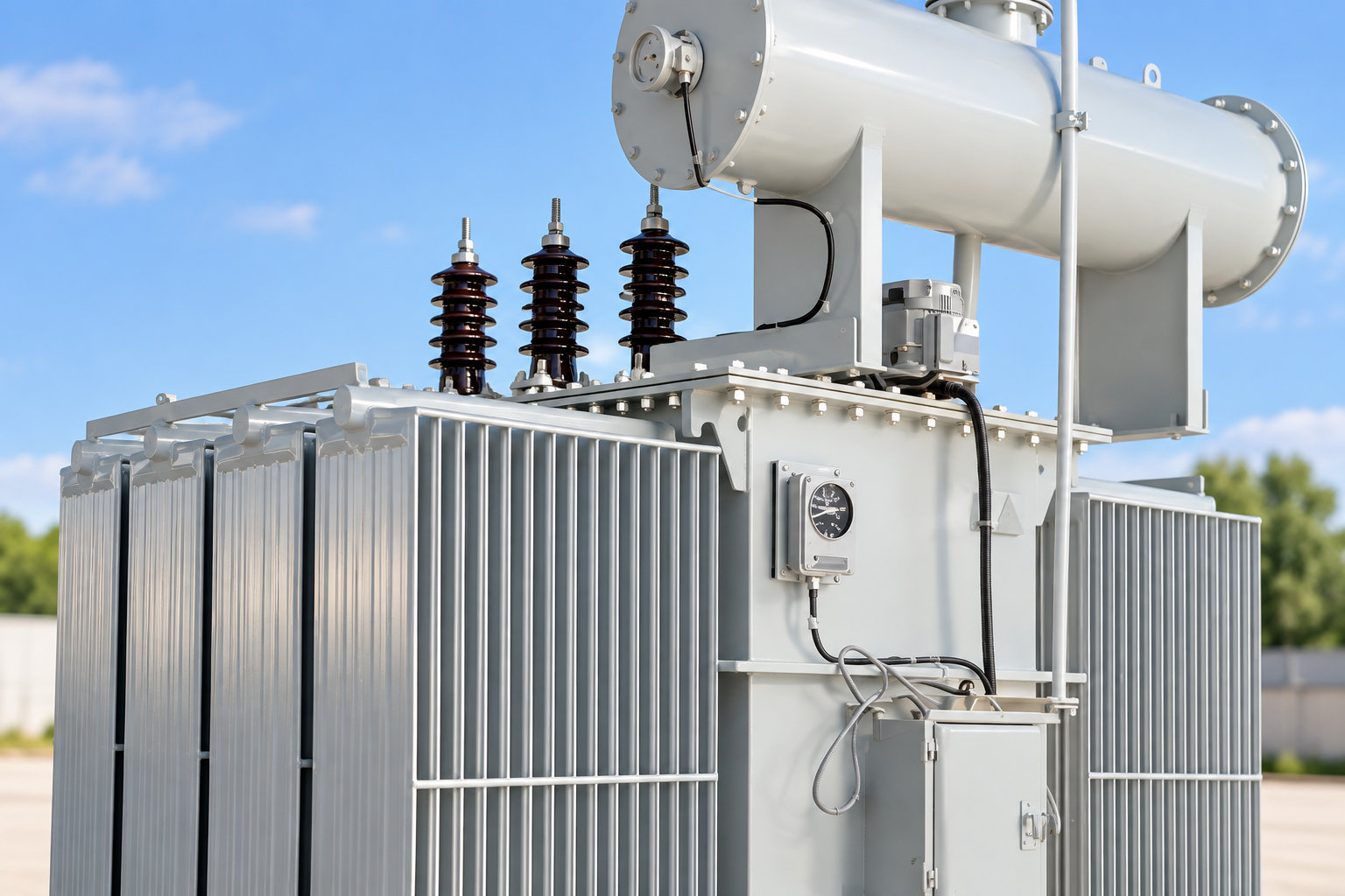
When discussing an LBAJI 35kV oil-immersed transformer, specify the required diagnostic records and delivery responsibilities in the project enquiry. Request the proposed test scope, agreed method, baseline file format, connection documentation and criteria for handling discrepancies. Product photographs establish external appearance; they do not establish that an individual transformer has passed SFRA or reveal its internal winding condition.
The enquiry should distinguish factory testing from site receiving tests and later maintenance diagnostics. Identify who will retain raw files, who will review abnormal results and how transport configuration will be documented. If a diagnostic service or test provision is required, obtain written confirmation of its availability and scope rather than assuming it is included with every product.
Preserve a baseline that future engineers can use
Store the original data in an asset-specific archive alongside the approved report, setup photographs, instrument identification and relevant event history. Retain earlier baselines when later tests are added. Replacing the original with the newest screenshot can remove the only evidence of the condition before transport or a fault.
A useful conclusion identifies whether the comparison is valid, summarizes confirmed differences and records the responsible reviewer’s disposition. Any limitation should be explicit: missing baseline, changed configuration, uncertain sequence or incomplete corroboration. The goal is a traceable assessment that supports a decision today and remains understandable during the next outage.
Questions to resolve before closing the work order
Check that the report and original files use the same terminal labels and that every plotted comparison can be traced to a saved measurement. Confirm that the reference and current files are not accidentally reversed or drawn from different taps. These are administrative checks with direct technical consequences: an attractive overlay can still compare the wrong records.
The closure record should identify unresolved items and their owner. If an additional measurement is required, record why it is needed and how it will address the uncertainty. If the equipment is released for service, retain the authorized decision with its supporting evidence. Completion of a test file by itself is not the same as an engineering release.
Pertanyaan yang sering diajukan
Does a changed SFRA trace prove winding movement?
No. A changed trace requires investigation, including baseline compatibility, connection records, repeatability and complementary diagnostic evidence before a defect is assigned.
Can SFRA be used without a factory baseline?
It may still provide useful information using justified phase or similar-unit comparisons, but the limitations must be documented and an appropriate baseline should be preserved for future use.
Does SFRA replace winding resistance or turns-ratio testing?
No. These tests investigate different electrical characteristics. The responsible engineer selects complementary tests according to the event, transformer design and assessment objective.
Can a product photograph confirm an SFRA pass?
No. A photograph shows visible equipment only. Test acceptance requires records for the identified transformer, the applicable procedure and an authorized assessment.
Related equipment and guides
- LBAJI 35kV oil-immersed power transformer
- Panduan Lengkap Dasar-Dasar Transformer
- Transformer Winding Resistance Test: Temperature, Tap Position and Report Review
- Transformer Turns Ratio Test: Nameplate, Tap Schedule and Result Review
Technical references
- Bureau of Reclamation: Transformers, Basics, Maintenance and Diagnostics (2005; historical diagnostic background)
- IEC 60076-18:2012: Measurement of frequency response (published scope)
- HSE HSG85: Electricity at work, safe working practices
Further learning: Frequency response concepts
This NPTEL university lesson explains frequency response as a general systems concept. It supports understanding why response changes with frequency; it is not a transformer SFRA connection procedure, diagnostic interpretation tutorial or source of acceptance limits. Source: NPTEL-NOC IITM.