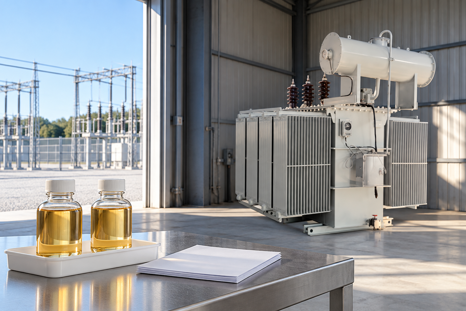
A transformer turns ratio test compares the measured transformation ratio with the value expected for the identified windings, connection and tap position. It helps verify that the transformer matches its design and can contribute to investigation of winding or tap-related problems. A useful report states the terminal arrangement, expected ratio calculation, measured ratio, test conditions and assessment basis. For a three-phase transformer, dividing the two nameplate line voltages is not always enough to obtain the winding ratio that the instrument should report: connection relationships and the instrument’s measurement convention also matter.
Decide what question the test must answer
A factory witness test, a receiving inspection and a diagnostic investigation may use similar instruments while answering different questions. A factory report can demonstrate conformity to an agreed design and specification. A site comparison can help identify whether the installed unit and selected taps match the project documents. A diagnostic test investigates a suspected change alongside operating history and other measurements. The scope should state which of these purposes applies.
A ratio result cannot establish every aspect of transformer condition. It does not replace insulation assessment, winding resistance, loss measurements or a protection review. Nor does a correct ratio prove that the transformer is appropriately sized for the load. Keep the report conclusion within its evidence: the measured ratio agreed with a stated expectation under stated conditions, or an exception remains for investigation.
Start with the approved nameplate and drawings
Record the transformer serial number, rated voltages, winding connections, frequency and tap schedule from the approved equipment documents. Confirm that the report belongs to the actual unit rather than a similar model from the same order. The terminal markings used by the test team should correspond to the connection drawing. A photograph of the nameplate can help resolve a transcription question, provided it is readable and belongs to the same asset.
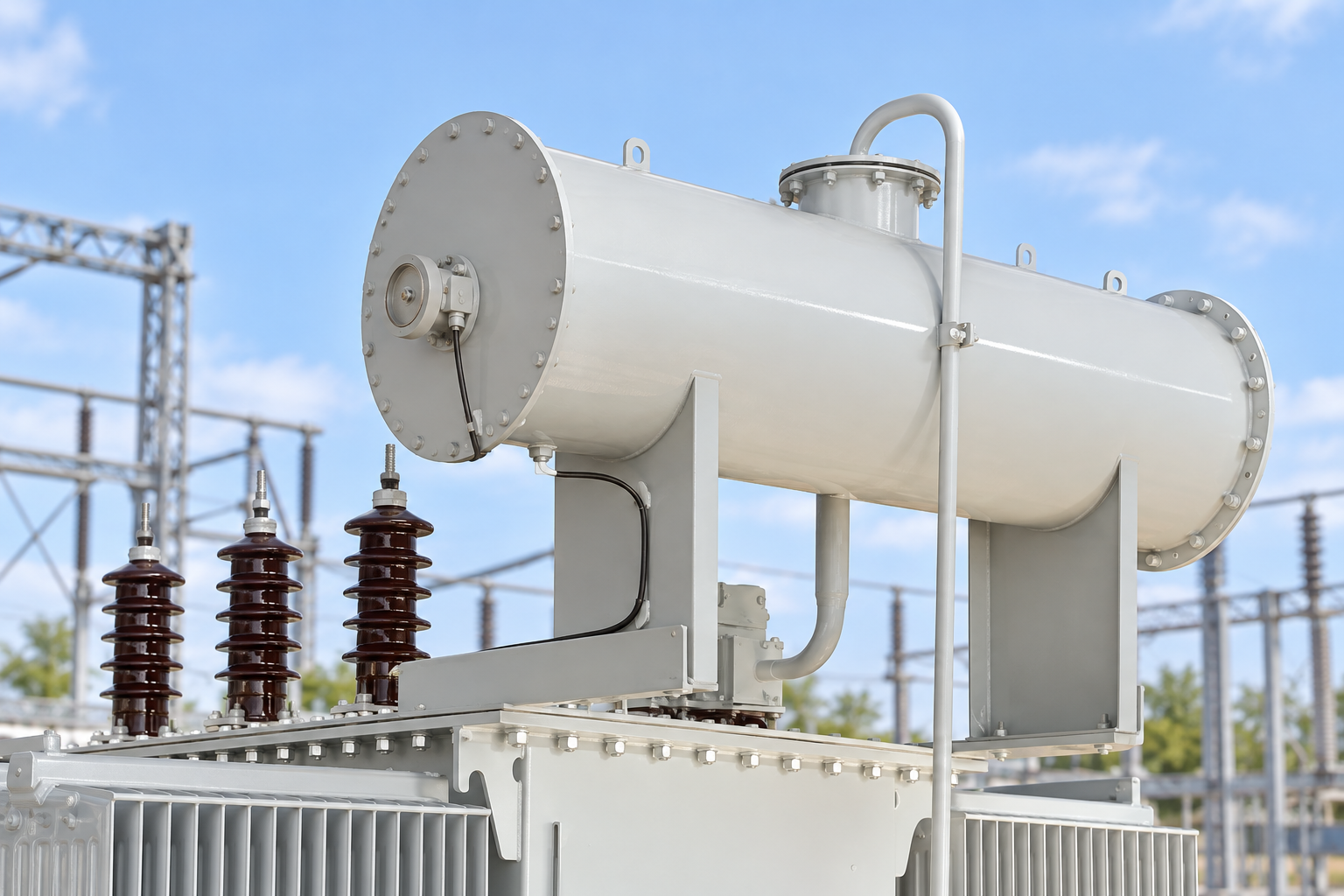
Itu LBAJI 35kV oil-immersed transformer product family provides an equipment context for this discussion. Its reference photograph does not reveal the ordered voltage ratio, vector group, terminal scheme or tap range. Those details must come from the project-specific data sheet and approved nameplate. A product-family description is therefore an input for an inquiry, not a replacement for the documents used to calculate expected test results.
Separate voltage ratio from winding turns ratio
For an ideal single-phase transformer, the winding voltage ratio follows the turns ratio: a = N1 / N2 = V1 / V2. Here a is dimensionless, N1 and N2 are winding turns, and V1 and V2 refer to the corresponding winding voltages. The equation is a basic model; a real test still requires the correct terminal pairing and approved measurement conditions. NPTEL‘s transformer equivalent-circuit material provides background on this relationship.
Three-phase nameplates commonly state line-to-line voltages, while a measurement or calculation may refer to phase windings. In a star connection, the balanced line-to-line voltage is the phase voltage multiplied by the square root of three. In a delta connection, the line-to-line voltage equals the phase winding voltage. An expected winding ratio must use compatible quantities on both sides and account for the selected connections.
For a hypothetical delta/star transformer rated 11,000 V to 415 V line-to-line, the line voltage ratio is about 26.506. The corresponding ideal winding ratio is 11,000 divided by (415 / square root of three), approximately 45.91. These values illustrate the difference between conventions; they are not specifications or measured results for an LBAJI transformer. A tester may display a compensated line ratio or another defined representation, so its instructions and configured vector group must be checked before comparing either number.
Build the expected tap schedule before testing
Every tested tap needs an expected ratio associated with the correct tap designation. A schedule should identify which winding is tapped and how the rated voltage changes at each position. Do not assume that a higher position number always means more turns or a higher output voltage. The designation and operating effect depend on the transformer design and the way the supply is applied.
A reviewer should be able to trace a row from the tap position on the mechanism to the approved schedule and then to the expected ratio entered in the report. If the factory and site teams use different names, provide a mapping rather than silently renaming the recorded positions. The as-found and final service positions should remain visible. Any tap operation must follow the equipment-specific procedure; this reporting guide is not an instruction to operate an off-circuit or on-load tap changer.
State what the instrument actually measures
Request the instrument manufacturer, model, serial number, calibration status and adopted test method. The record should explain whether the displayed result is a raw winding ratio, a compensated voltage ratio or another defined output. Relevant vector-group and terminal settings should be available for review. An automatic report can still be misleading when the wrong connection model or nominal ratio was entered at the start.
The applied test voltage and frequency should be recorded with any method-specific limitations. Do not choose a universal test voltage from an online example or substitute normal service voltages into a portable test procedure. The competent team must use suitable equipment and the approved safe working arrangements. An inaccessible neutral, an unusual winding arrangement or connected accessories may require specific manufacturer guidance rather than a standard worksheet copied from another asset.
Review phase identity and displacement separately
A ratio magnitude and a phase relationship are connected aspects of transformer identification, but they are not interchangeable statements. A report should show which phases and terminals were paired, how the connection was configured and whether phase displacement or vector-group checks formed part of the agreed scope. A single ratio number cannot demonstrate that every terminal identification and phase relationship was verified.
If the displayed ratio appears correct but the phase relationship is unexpected, preserve both observations and ask the responsible engineer to review the configuration and documentation. Do not re-label the terminals simply to make the report look consistent. The approved drawings, physical markings, instrument convention and actual observations must be reconciled before the project signs off the connection-related part of acceptance.
Ratio-report review table
This table is a qualitative document checklist. Its purpose is to prevent comparison errors; it does not define a standard tolerance or prescribe field connections.
| Record | Required detail | Pertanyaan review |
|---|---|---|
| Equipment identity | Serial number and approved drawing revision | Is this the transformer supplied to the project? |
| Ratio basis | Line or winding voltage convention | Does the expected value match the instrument display basis? |
| Connection | Vector group and terminal pairing | Were star and delta relationships handled correctly? |
| Tap schedule | Position and expected value for every tested row | Is the correct winding and tap designation being used? |
| Test conditions | Instrument, voltage, frequency and configuration | Are repeated results genuinely comparable? |
| Assessment | Adopted criterion, deviation and exceptions | Has an authorized engineer resolved unusual results? |
Calculate a deviation without inventing a limit
A transparent expression is deviation (%) = 100 × (measured ratio − expected ratio) / expected ratio. Both ratios must use the same direction and convention, and the expected ratio must be nonzero. Some reports show an absolute deviation instead of a signed value; the report should identify that choice. A ratio expressed as high-to-low cannot be compared directly with its low-to-high reciprocal.
For a hypothetical expected ratio of 20.000 and measured ratio of 20.040, the signed deviation is +0.20%. This is an arithmetic illustration, not a pass result or a universal permissible difference. The acceptance criterion must come from the current adopted specification and equipment requirements. Record the criterion’s reference and edition so that a future reviewer can understand why the original team accepted or investigated the result.

Investigate a mismatch in a controlled order
Before diagnosing a winding problem, check the asset identity, tap position, ratio direction, line-versus-phase conversion and instrument connection settings. Review whether the expected schedule was copied correctly and whether the reported terminal labels match the drawings. These checks often require no change to the equipment and can expose a documentation problem that would otherwise be mistaken for a physical defect.
If the discrepancy remains, the competent team should assess setup suitability and repeatability under the approved procedure. Preserve the original and repeat records with an explanation of what changed. A recurring unexplained difference may justify further diagnostic work or manufacturer review, but the ratio alone does not locate the defect. Winding resistance, excitation current and other relevant evidence should be evaluated as complementary information rather than selected only when they support a preferred conclusion.
Keep site testing within a planned safe system
A transformer can be isolated from its normal source while still being affected by other connected circuits or by voltages introduced during testing. The test plan must address the actual installation, access controls, isolation arrangements and the hazards associated with the chosen equipment. HSE HSG85 provides a general safe-working framework; it does not supply the transformer-specific connection or operating procedure.
Do not use a training diagram as a field switching instruction. University demonstrations explain principles under controlled teaching conditions. They do not authorize energizing an installed transformer or establish safe clearances for a site. Buyers should request competent personnel, a reviewed method and the required permits as part of the service scope, with clear responsibility for restoring and documenting the equipment after testing.
Prepare a useful purchase and handover package
Ask the supplier to identify the factory ratio-test scope, the tap positions covered, expected values, terminal convention and report format before the order is finalized. If site comparison is planned, agree which factory records will be available to the commissioning contractor. Include the latest approved nameplate and connection diagram in the handover package so that the test team does not reconstruct the intended configuration from an old sales quotation.
The final report should separate raw observations, calculated deviations, acceptance criteria and engineering decisions. Outstanding exceptions need an owner and a documented next action. If a revised drawing or a corrected instrument setting resolves the issue, retain the earlier record and the reason for revision. That evidence trail is more useful for future maintenance than a clean-looking table with unexplained replacement values.
Pertanyaan yang sering diajukan
Is the nameplate voltage ratio always the measured turns ratio?
No. Three-phase line voltages, phase winding voltages and instrument compensation can use different conventions. Confirm the connection and display basis first.
Should all tap positions have the same ratio?
No. A tap arrangement intentionally changes the selected winding turns. Compare each tested position with its own approved expected value.
Does a correct ratio prove the transformer is healthy?
No. Ratio testing addresses a limited part of the assessment. Other electrical, insulation and condition evidence may still be required.
Can a small percentage deviation be accepted automatically?
No. Acceptance depends on the adopted specification, method, transformer configuration and measurement conditions. An example percentage is not a universal tolerance.
Related equipment and guides
- LBAJI 35kV oil-immersed power transformer
- Panduan Lengkap Dasar-Dasar Transformer
- Transformer Testing: Methods, Procedures & Test Checklist
- Uji Penerimaan Pabrik untuk Transformator Daya: Daftar Periksa Saksi Importer
Technical references
- Bureau of Reclamation: Transformers, Basics, Maintenance and Diagnostics (2005; historical background)
- NPTEL Power System Analysis: Transformer Model
- HSE HSG85: Electricity at work, safe working practices
Further learning: Ideal transformer and phase relationships
This IIT Kharagpur NPTEL lecture explains the ideal transformer, dot convention and phasor diagram. It supports the discussion of ratio conventions and corresponding winding quantities. It is educational background, not a portable ratio-tester demonstration or site connection instruction. Source: NPTEL IIT Kharagpur.

Watch Lecture 03: Ideal Transformer, Dot Convention and Phasor Diagram