Circuit breakers, protection relays and busbars form the operating core of an electrical distribution system. The breaker interrupts current, the relay decides when interruption is necessary, and the busbar carries power between incoming and outgoing circuits. Selecting them independently can produce nuisance trips, inadequate fault clearing or equipment that cannot withstand the available short-circuit current. This guide explains how the three elements work together and how to specify them for a safe, maintainable system.
What Is a Circuit Breaker?
A circuit breaker is a reusable switching and protective device. It carries normal load current, makes and breaks operating current, and interrupts abnormal current within its rated capability. Unlike a fuse, it can normally be reset after the fault has been investigated. However, “circuit breaker” covers devices ranging from a small branch-circuit MCB to a withdrawable medium-voltage vacuum circuit breaker. Their ratings and applications are not interchangeable.
The most important selection data are rated voltage, continuous current, frequency, breaking current, making current, short-time withstand current, operating sequence and insulation level. The installation must also consider ambient temperature, altitude, enclosure protection, control voltage and the applicable IEC or project standard.
Common Circuit Breaker Types
MCB, MCCB and air circuit breakers
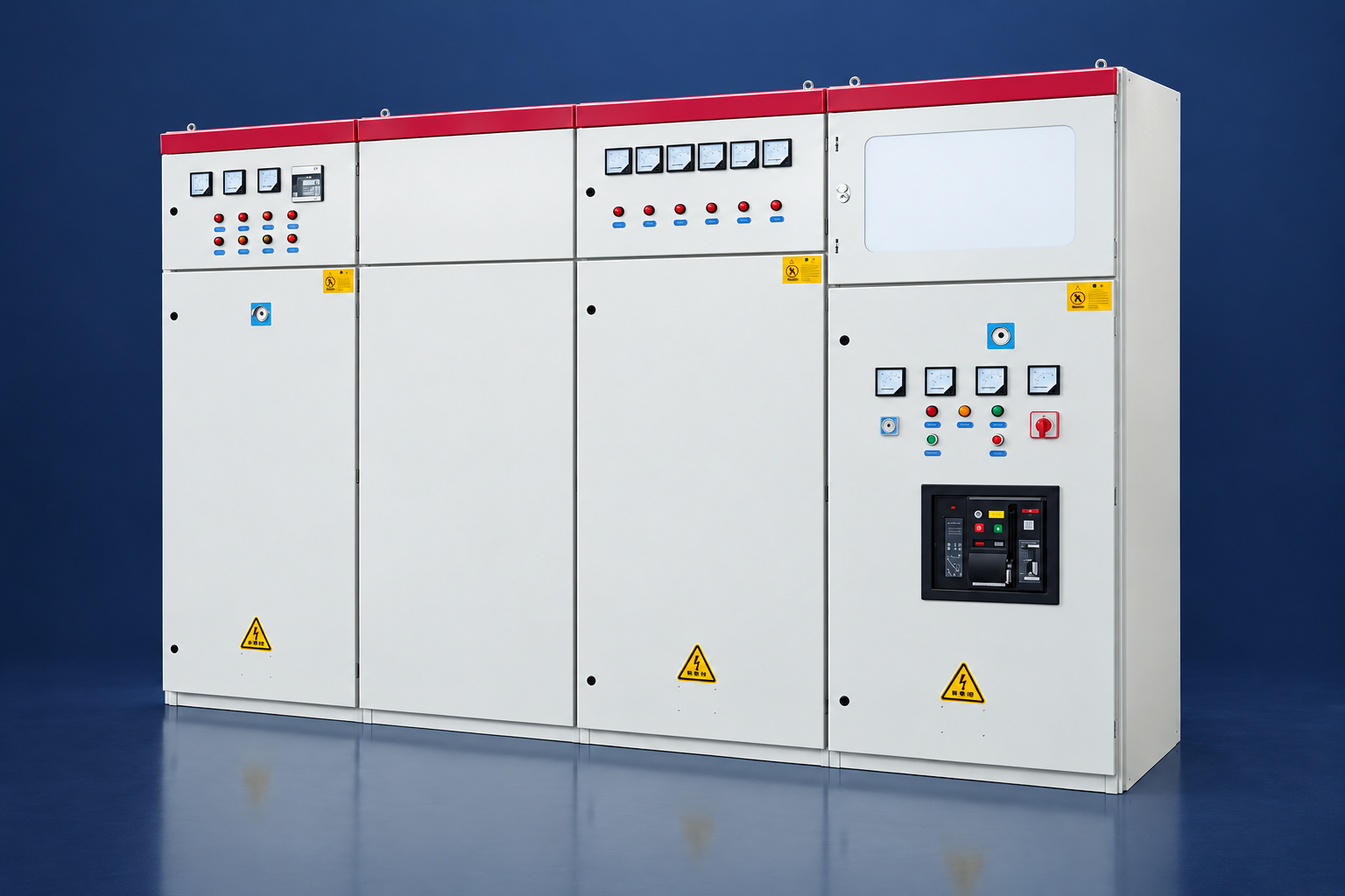
A miniature circuit breaker (MCB) protects final low-voltage circuits and usually combines thermal overload and magnetic short-circuit elements. A molded-case circuit breaker (MCCB) covers higher currents and often provides adjustable electronic trip settings. An air circuit breaker (ACB) is commonly used as the main or bus-coupler breaker in low-voltage switchboards. Engineers should check both ultimate and service breaking capacity and coordinate the trip curve with downstream devices.
AFCI, RCCB and dual-function devices
An AFCI circuit breaker detects characteristic arcing patterns in branch wiring. A residual-current circuit breaker detects leakage current that may create shock or fire risk. A dual-function breaker can combine arc-fault and ground-fault protection. These are building-level low-voltage devices; they do not replace the overcurrent relay and primary breaker used in medium-voltage industrial switchgear. Local electrical codes determine where AFCI or residual-current protection is mandatory.
Vacuum and SF6 circuit breakers
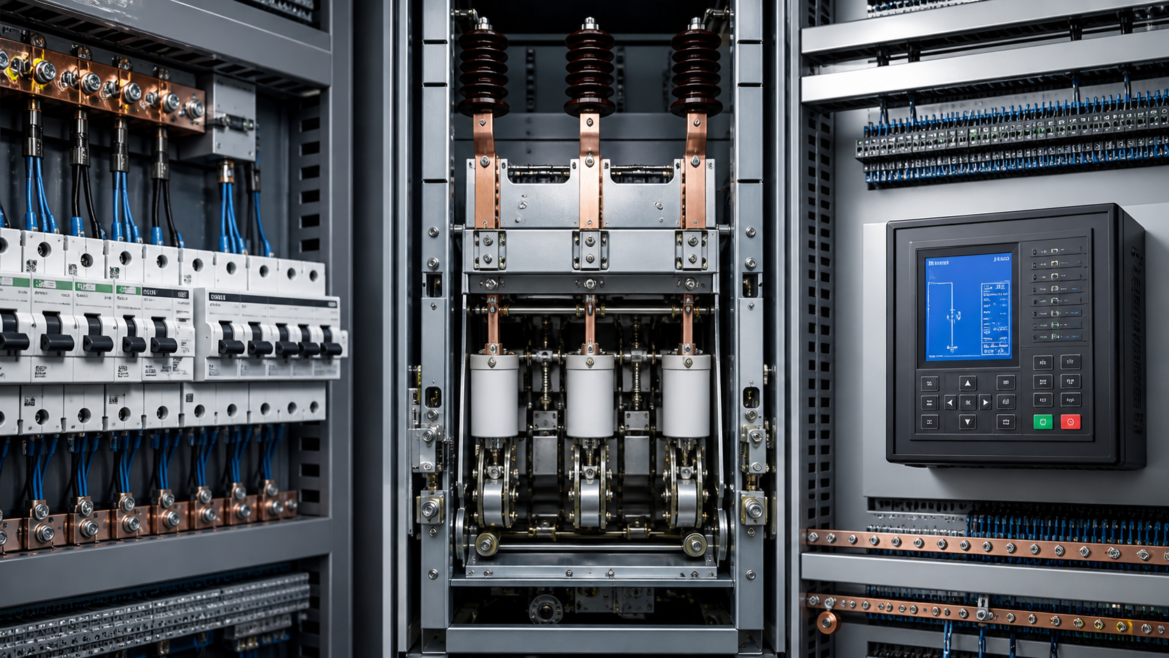
Vacuum circuit breakers extinguish the arc inside sealed vacuum interrupters and are widely used in medium-voltage metal-clad switchgear. They offer high mechanical life and relatively low routine maintenance. SF6 circuit breakers use gas for insulation and arc interruption and have historically served higher-voltage duties, although environmental policy increasingly favors lower-GWP alternatives. Product choice must reflect voltage, fault level, switching duty and lifecycle requirements—not only initial price.
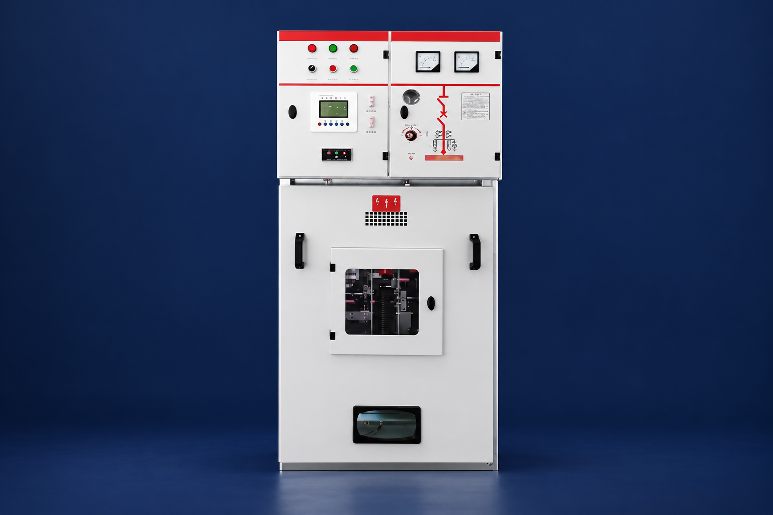
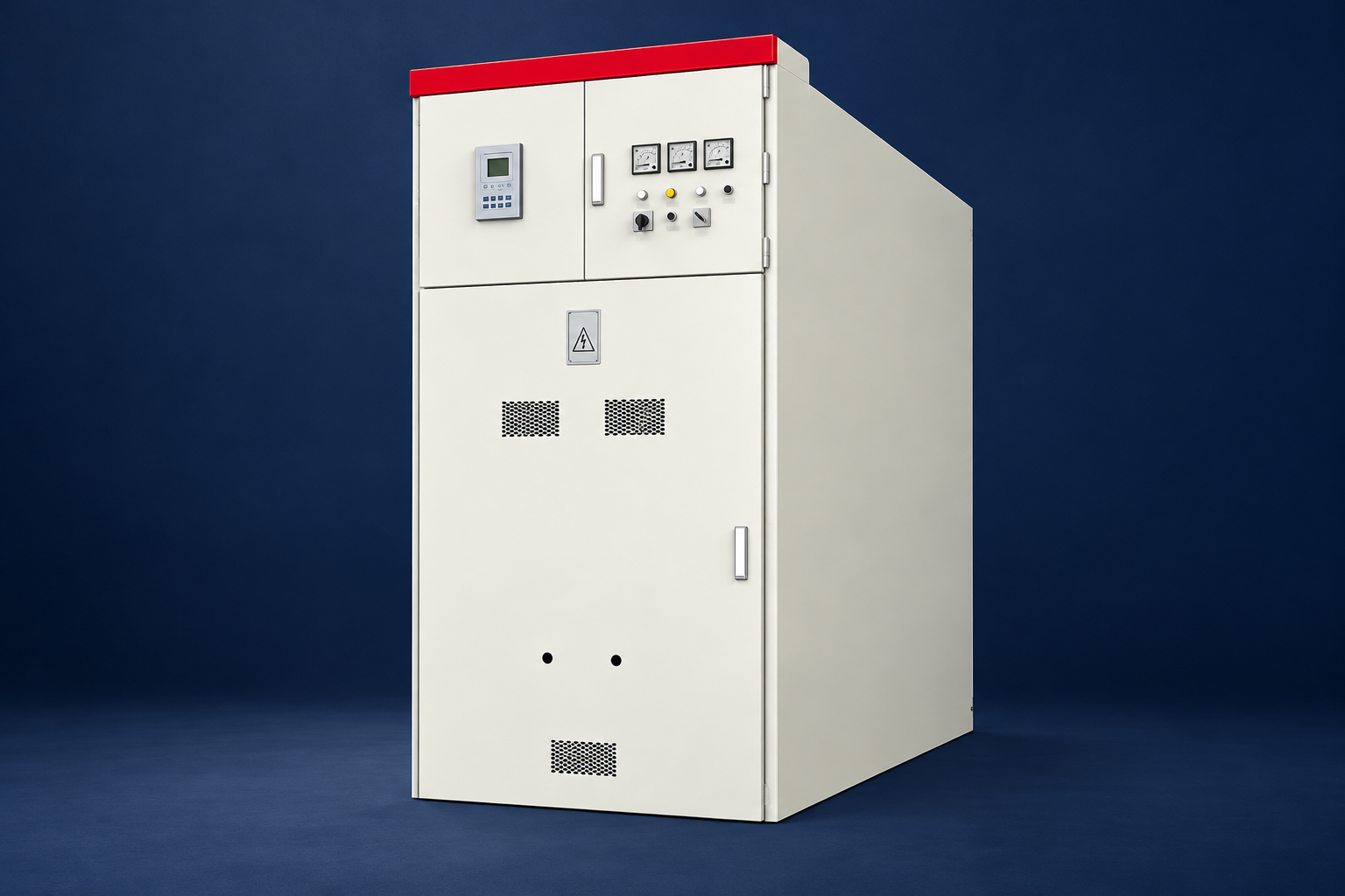
For a typical withdrawable medium-voltage arrangement, see LBAJI’s KYN28A-12 metal-enclosed switchgear. For 40.5 kV projects, the KYN61-40.5 switchgear illustrates a higher-voltage metal-clad platform.
Quick Comparison and Selection Table
Use this table as a quick review of the main engineering and procurement decisions explained in the article.
| Decision area | Practical meaning | What to verify |
|---|---|---|
| What Is a Circuit Breaker? | A circuit breaker is a reusable switching and protective device. | It carries normal load current, makes and breaks operating current, and interrupts abnormal current within its rated capability. |
| Common Circuit Breaker Types | A miniature circuit breaker (MCB) protects final low-voltage circuits and usually combines thermal overload and magnetic short-circuit elements. | A molded-case circuit breaker (MCCB) covers higher currents and often provides adjustable electronic trip settings. |
| How Protection Relays Control Breaker Operation | Instrument transformers reproduce primary current and voltage at safe secondary levels. | The protection relay samples those signals, applies protection logic and energizes the trip coil when its criteria are met. |
| Busbars: The Shared Power Path | An electrical busbar is a low-impedance conductor that distributes power between circuits. | Copper is common because of its conductivity and mechanical strength; aluminum may reduce weight and cost but requires different joint design and surface treatment. |
| Understanding Circuit Breaker Symbols | A circuit breaker symbol on a single-line diagram identifies the switching point, but the drawing legend controls the exact notation. | An MCB circuit breaker symbol on a building diagram may differ from the symbol used for a medium-voltage withdrawable breaker. |
How Protection Relays Control Breaker Operation
Instrument transformers reproduce primary current and voltage at safe secondary levels. The protection relay samples those signals, applies protection logic and energizes the trip coil when its criteria are met. The breaker then opens the power circuit. A complete trip chain therefore includes CTs or sensors, wiring, auxiliary supply, relay output contacts, trip coil, breaker mechanism and status feedback.
Typical functions include phase overcurrent, earth fault, directional overcurrent, under/overvoltage, frequency, transformer differential, restricted earth fault and breaker failure protection. Function numbers alone do not prove adequate protection. Settings must be based on load current, transformer inrush, motor starting, conductor limits, minimum and maximum fault current, CT performance and upstream/downstream clearing times.
Protection coordination and selectivity
Selectivity means the device closest to the fault clears it while healthy parts remain energized. A coordination study plots time-current curves and checks instantaneous elements, grading margins and equipment damage curves. Zone-selective interlocking or differential protection may reduce clearing time where ordinary time grading would expose the busbar to excessive arc energy.
Busbars: The Shared Power Path
An electrical busbar is a low-impedance conductor that distributes power between circuits. Copper is common because of its conductivity and mechanical strength; aluminum may reduce weight and cost but requires different joint design and surface treatment. A busbar rating is more than its cross-sectional area. Enclosure ventilation, ambient temperature, plating, joint resistance, phase spacing and proximity effects all influence temperature rise.
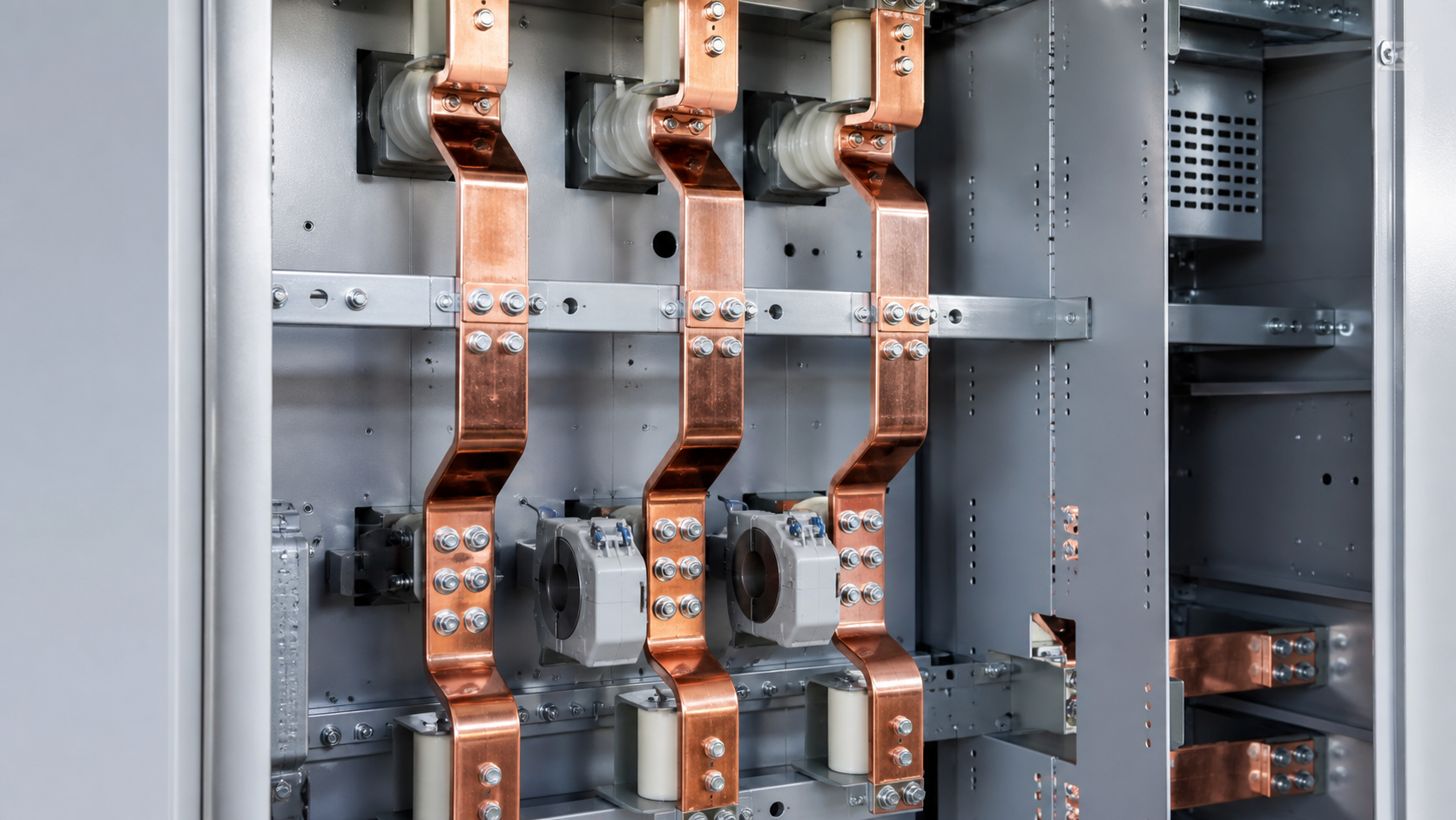
Short-circuit duty has a thermal component and an electrodynamic component. The busbar, supports and joints must survive the specified current for the specified duration without unacceptable deformation or insulation damage. Engineers should verify rated short-time withstand current, rated peak withstand current, test duration and the actual available fault level at the installation.
Busbar arrangements
Single-bus systems are economical and simple. Sectionalized single bus arrangements improve continuity by limiting a fault or maintenance outage to one section. Double-bus and transfer-bus schemes provide more operating flexibility but add breakers, disconnectors, interlocking and protection complexity. The correct arrangement comes from the required reliability, operating philosophy and maintenance plan.
Understanding Circuit Breaker Symbols
A circuit breaker symbol on a single-line diagram identifies the switching point, but the drawing legend controls the exact notation. An MCB circuit breaker symbol on a building diagram may differ from the symbol used for a medium-voltage withdrawable breaker. The single-line diagram should also show device identifiers, CT ratios, relay functions, earthing switches, disconnectors, bus sections and interlocks. Never infer a breaker’s interrupting rating or protective function from its symbol alone; use the equipment schedule and protection drawings.
How to Select a Coordinated Breaker–Relay–Busbar System
- Define the system: nominal and maximum voltage, frequency, earthing method, source impedance and future expansion.
- Calculate load current: include demand, diversity, transformer capacity, motor starting and planned spare capacity.
- Calculate fault current: check maximum duty for withstand and interruption, plus minimum fault current for relay sensitivity.
- Select breaker ratings: verify insulation, continuous current, breaking/making current, operating duty and mechanical class.
- Design the busbar: verify temperature rise, short-time and peak withstand, joints, supports and compartmentation.
- Choose CTs and relays: match ratios, burden, accuracy and saturation performance to metering and protection duties.
- Coordinate settings: demonstrate selectivity and verify equipment protection and arc-flash clearing time.
- Confirm interfaces: control supply, communications, remote I/O, mechanical/electrical interlocks and SCADA signals.
Compact distribution projects may use a ring main unit such as the LBHB-12 environmentally friendly gas-insulated RMU. For installations where compact sealed insulation is important, review the HC-40.5 fully insulated switchgear. Final configuration must always be matched to the approved single-line diagram and fault study.
Testing and Commissioning
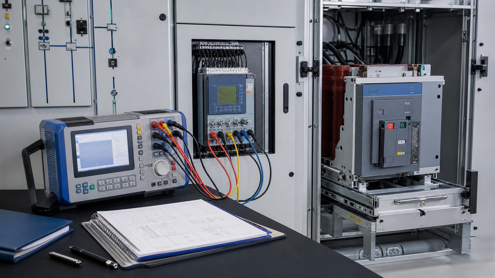
Factory and site tests should prove both individual equipment and the complete operating chain. Typical checks include insulation resistance, power-frequency withstand where applicable, contact resistance, mechanical operation, interlocks, timing, CT polarity, secondary injection, primary injection, trip-circuit supervision and remote control. Protection tests should record pickup, operating time, logic, outputs and the actual breaker trip response.
Maintenance and Replacement
Do not replace a panel circuit breaker by matching only frame size or appearance. Confirm voltage, poles, interrupting rating, trip characteristics, mounting, bus connection, control voltage and approved compatibility. Medium-voltage maintenance should include mechanism inspection, operation count review, contact wear assessment, insulation cleaning, lubrication according to the manufacturer, relay self-diagnostics and periodic functional trips. Thermographic inspection can reveal abnormal resistance at busbar joints before visible damage occurs.
Opening a circuit breaker box, removing a breaker or working inside switchgear exposes personnel to shock and arc-flash hazards. Isolation, lockout/tagout, absence-of-voltage verification, grounding and appropriate PPE must follow local rules and the site’s electrical safety program. This guide is for system planning and procurement, not a substitute for qualified electrical work.
How a circuit breaker interrupts an arc
Opening contacts do not stop current instantly because an arc forms between them. The interrupter cools, divides, stretches or extinguishes that arc, while the insulation system withstands the recovering voltage. Air, vacuum and gas interrupters use different techniques, so voltage class, interrupting current and transient-recovery duty must all match the circuit.
Standard ratings and smart circuit breakers
A useful breaker specification states rated voltage, continuous current, frequency, poles, interrupting capacity, making or close-and-latch duty, operating sequence and trip-unit functions. Connected or smart breakers add metering, alarms and communications, but digital features do not compensate for inadequate fault rating, poor selectivity or an unsuitable protection curve.
Technical references and further reading
The following independent sources support the standards, terminology, calculations, and safety context discussed in this guide:
- IEC 62271-200 metal-enclosed switchgear standard — Scope, classifications, service conditions, internal-arc testing, interlocks, and requirements for AC metal-enclosed switchgear up to 52 kV.
- IEEE C37.121 guide for switchgear-unit substations — Coordination guidance for switchgear and transformer sections in three-phase unit substations.
- OSHA electrical power safety requirements — Safety requirements for construction involving electric power transmission and distribution equipment.