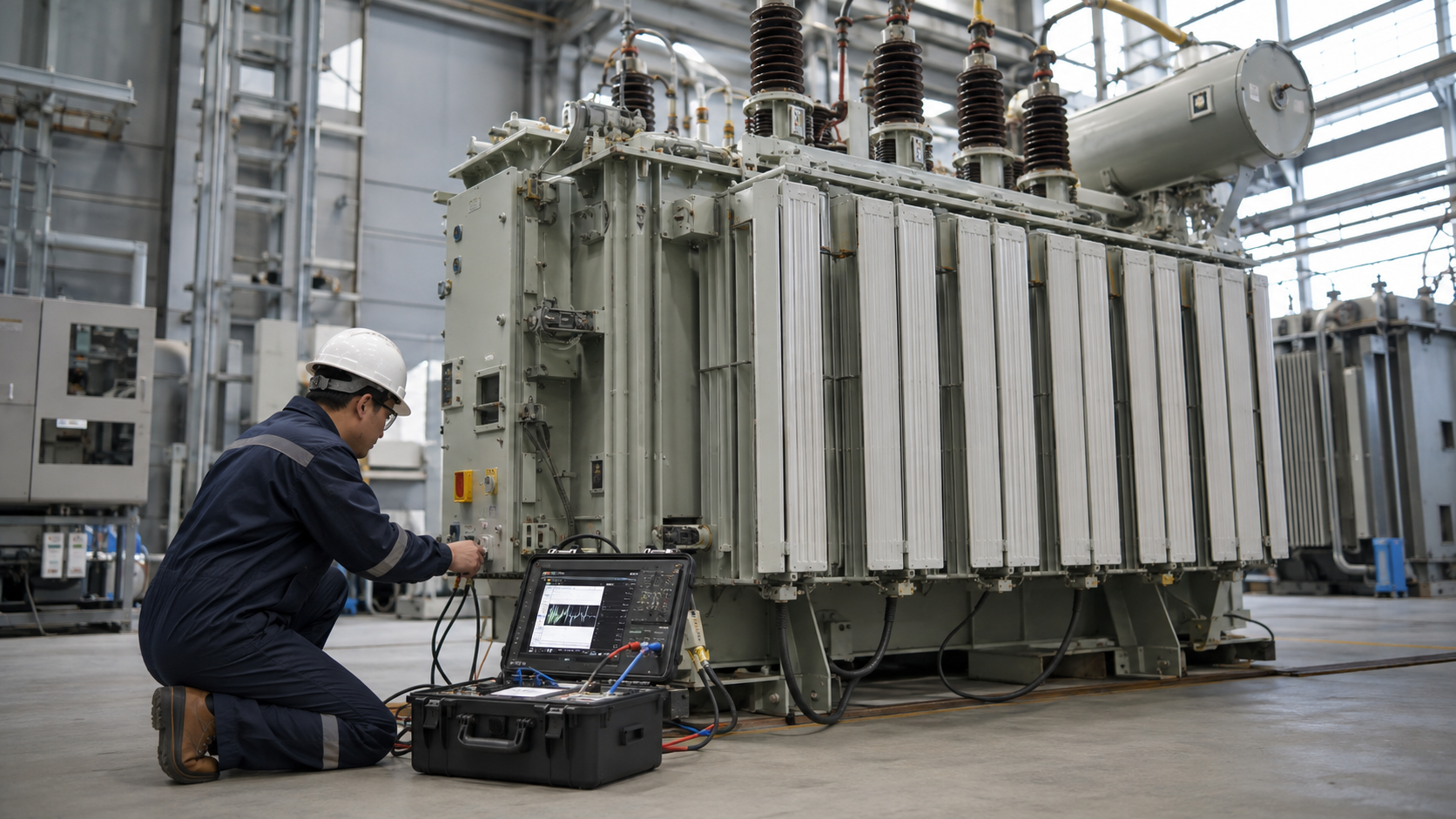
Transformer capacity is the amount of apparent power, in kilovolt-amperes (kVA), a transformer is rated to supply under specified operating conditions. To choose a suitable rating, calculate the load in kVA, then check voltage, phase, load behavior, environment and the project’s documented growth or backup requirements. This guide focuses on that capacity decision; for representative rating examples and physical dimensions, see our standard transformer sizes guide.
What Transformer Capacity Means
A transformer’s nameplate kVA is not a promise that every installation can use that amount in every condition. It is tied to its rated winding voltage and frequency, insulation and temperature-rise design, cooling method, and specified ambient and altitude conditions. The applicable product standard and manufacturer documentation define the rating basis for the particular unit.
Capacity is stated in kVA rather than only in kilowatts (kW) because transformer current and voltage determine winding and core demands, while a load’s power factor determines how much of its apparent power becomes real power. At a power factor of 0.90, for example, 100 kVA corresponds to 90 kW of real power at the same electrical point. The power factor does not change the transformer’s nameplate kVA; it changes the kVA needed to supply a stated kW load.
Schneider Electric’s capacity-calculation guidance likewise bases required transformer kVA on voltage and current, with phase included. For broader rating and requirement terminology, consult the official scope of IEEE C57.12.00 for covered liquid-immersed transformers.
Transformer Capacity Calculation Formulas
Use values from the same side of the transformer and the correct phase arrangement. For a balanced three-phase system, use line-to-line voltage and line current:
| Known load data | Capacity formula | Important input |
|---|---|---|
| Single-phase voltage and current | kVA = V × I ÷ 1,000 | Use the voltage across the single-phase load. |
| Balanced three-phase voltage and current | kVA = √3 × VLL × IL ÷ 1,000 | Use line-to-line voltage and line current. |
| Real power and power factor | kVA = kW ÷ power factor | Use the demand kW and power factor measured or specified at the same point. |
For a single-phase load, the relation is also described as S = V × I. For balanced three-phase power, S = √3 × VLL × IL. The MIT OpenCourseWare power-systems notes explain apparent power and its relationship to real power and power factor.
Worked Example: Convert Demand kW to Required kVA
Suppose a facility’s documented maximum demand is 108 kW at a measured power factor of 0.90. The apparent demand is 108 ÷ 0.90 = 120 kVA. If an approved load forecast adds 15% for a specific planned expansion, the planning figure becomes 120 × 1.15 = 138 kVA. A designer can then compare that result with suitable manufacturer ratings and verify all operating conditions. The 15% is an example from this scenario—not a universal transformer-sizing margin.
Before applying any growth factor, check what the load study already includes. Do not add a second allowance for growth, diversity or spare capacity if it has already been built into the documented maximum demand. For a full building or process load schedule, use our transformer sizing calculation guide; when you already know amps, voltage and phase, the amps-to-kVA calculator can convert those inputs to apparent load.
Check the Inputs Before Choosing a Capacity
- Demand, not just connected load: use a credible maximum-demand or load-profile estimate and document any demand or diversity assumptions.
- Voltage and phase: confirm the primary and secondary voltages, frequency, phase count, and whether the stated voltage is line-to-line or line-to-neutral. See our single-phase transformer guide if the application is single-phase.
- Power factor and load type: include the actual or specified power factor for kW loads. Motors, rectifiers, variable-frequency drives and other nonlinear loads may need additional engineering review.
- Starting and changing loads: motor starts, cyclic duty, welding loads and rapid load changes can cause current or voltage effects that a steady-state kVA sum does not show.
- Balance and harmonics: phase imbalance or harmonic currents can increase heating in windings and neutral paths. Do not assume the balanced three-phase formula alone captures these effects.
- Installation and operation: confirm ambient temperature, altitude, enclosure, ventilation and cooling method against the manufacturer’s rating conditions.
- Project requirements: state future expansion, redundancy, emergency operation, efficiency targets and applicable local rules instead of applying a generic safety margin.
Loading guidance must match transformer type and operating conditions. IEC 60076-7:2018 addresses loading of mineral-oil-immersed transformers under varying ambient temperature and load; it is not a blanket overload allowance for every dry-type or liquid-filled unit. Ask the manufacturer and responsible electrical engineer to assess any overload or emergency-loading case.
Capacity Is Not the Same as Current or Physical Size
The same kVA rating gives different full-load current at different voltages and phase configurations. Calculate current from the transformer’s rated kVA and the voltage on the specific winding before selecting conductors or protective devices. Also distinguish steady load capacity from short-circuit withstand and protection settings: those require the actual impedance, system fault level and coordination study.
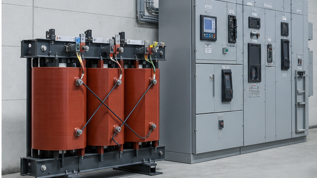
Physical dimensions cannot be derived from kVA alone. Voltage class, insulation clearances, cooling, enclosure, efficiency, impedance, terminals and accessories all affect the outline drawing. For dry-type construction and packaged distribution choices, compare our transformer types and construction guide, dry-type transformer range, and YBM-12 prefabricated substation. For a liquid-immersed power-transformer application, review the 35 kV oil-immersed transformer and confirm the required rating with the project team.
Transformer Capacity FAQs
How do you calculate transformer capacity in kVA?
For single phase, multiply voltage by current and divide by 1,000. For balanced three phase, multiply √3 by line-to-line voltage and line current, then divide by 1,000. If the load is stated in kW, divide demand kW by power factor.
Does power factor change a transformer’s kVA rating?
No. The nameplate kVA rating does not change with the connected load’s power factor. A lower power factor means a given kW demand requires more kVA and current.
How many kVA does a 100 kW load need?
It depends on power factor. At 0.90, 100 kW ÷ 0.90 is about 111.1 kVA before considering growth, starting behavior, harmonics, temperature, altitude or other project requirements.
Can a transformer operate continuously at its full nameplate kVA?
Only when the voltage, frequency, cooling and environmental conditions comply with the manufacturer’s rating basis. Confirm the specific nameplate and documentation; do not infer an overload allowance from the kVA value alone.
Does transformer capacity determine its physical dimensions?
No. kVA is one design input. Voltage class, construction, insulation, cooling, enclosure and accessories also affect dimensions, so use the approved project-specific outline drawing for installation.