A single-phase transformer transfers AC power between circuits through magnetic coupling. The right choice depends on more than a voltage ratio: the load’s apparent power, duty cycle, available supply, secondary arrangement, installation environment and protection all matter. This guide explains the operating principle, common forms, rating calculations and the information to confirm before requesting a quotation.
In brief: a transformer changes voltage and current in proportion to its winding turns; it does not create a new phase system. Its kVA rating describes apparent power, while the nameplate and project specification govern the actual voltage, frequency, temperature rise, insulation and installation limits.
What is a single-phase transformer?
A single-phase transformer has a primary winding connected to a single-phase AC source and one or more secondary windings that supply a load. The windings share a magnetic core but are electrically isolated from one another in an isolation transformer. Alternating primary current produces changing magnetic flux in the core; that flux induces an AC voltage in the secondary winding.
Distribution versions may serve a building, a rural line, a small commercial load, lighting, controls or an individual piece of equipment. The physical package varies: pole-mounted and pad-mounted liquid-filled units are intended for distribution networks, while dry-type units often serve indoor or equipment-room applications. A small control transformer is a separate application class. Do not assume that a product is suitable for a location just because its voltage and kVA appear to match.
How the operating principle works
For an ideal transformer, the voltage ratio is approximately the turns ratio:
V1 / V2 ≈ N1 / N2
where V is RMS voltage and N is the number of turns. A secondary with fewer turns than the primary is a step-down winding; one with more turns is step-up. In an ideal transformer, current changes in the inverse direction, so voltage is not increased without a corresponding reduction in available current at the same apparent power.
Real units have winding resistance, leakage reactance, core losses, temperature rise and voltage regulation. The equations are useful for estimates and load checks, not a substitute for the manufacturer’s guaranteed data or a protection study. A transformer also operates at the frequency and voltage for which its magnetic design is rated; applying the wrong frequency or overvoltage can cause excessive magnetizing current and heating.
Common single-phase transformer forms
“Single-phase” describes the AC supply arrangement, not the construction or mounting method. A buyer should identify each separately.
| Form | Typical context | What to verify |
|---|---|---|
| Pole-mounted distribution | Overhead distribution serving a local load or service area | Utility voltage, primary protection, bushing/terminal arrangement, mounting hardware, environmental and utility requirements |
| Pad-mounted distribution | Ground-level distribution installation where the network and access design call for it | Enclosure/access arrangement, primary and secondary compartments, fault protection, site clearances and applicable standards |
| Dry-type distribution | Indoor or equipment-room distribution, subject to enclosure and ventilation design | Insulation class, temperature rise, enclosure rating, cooling, sound and room conditions |
| Control or isolation transformer | Control circuits, instrumentation or electrical isolation within equipment | Duty, inrush, isolation requirements, grounding scheme, short-circuit withstand and control-circuit protection |
These are broad categories, not interchangeable product specifications. Liquid-filled and dry-type construction, core form, cooling method and connection arrangement must be taken from the applicable product data. For a broader overview, see our transformer types and construction guide.
Single-phase transformer ratings: kVA, voltage and current
For a single-phase circuit, apparent power is:
S (kVA) = V (V) × I (A) ÷ 1,000
Rearranging gives I (A) = 1,000 × S (kVA) ÷ V (V). Use the voltage of the winding whose current you are estimating. These are full-load apparent-current estimates; actual allowable load also depends on ambient conditions, cooling, harmonics, enclosure, operating profile and the manufacturer’s ratings.
For example, consider an illustrative 5 kVA, 240 V primary and 120 V secondary transformer. Its ideal full-load winding currents are about 20.8 A on the 240 V side and 41.7 A on the 120 V side. This is arithmetic, not a proposed equipment rating or a wiring instruction. A real selection must use a listed nameplate and the applicable design and installation rules.
| Check | Illustrative calculation or record | Why it matters |
|---|---|---|
| Apparent power | 5 kVA = 5,000 VA | Transformer capacity is normally stated in VA or kVA |
| Primary current estimate | 5,000 ÷ 240 ≈ 20.8 A | Estimate for the stated primary winding at rated apparent load |
| Secondary current estimate | 5,000 ÷ 120 ≈ 41.7 A | Estimate for the stated secondary winding at rated apparent load |
| Nameplate confirmation | Rated kVA, primary/secondary voltage, frequency, taps, temperature rise and connection diagram | Confirms the example assumptions match the actual unit and system |
kVA is not the same as kW. For a sinusoidal load, real power in kW is approximately kVA multiplied by power factor. At 5 kVA and 0.8 power factor, the real load is about 4 kW, but the transformer still carries current associated with 5 kVA. Motor starting, rectifiers, nonlinear loads and future expansion can change the required capacity. For a deeper sizing workflow, use our transformer sizing guide and kVA explainer.
Wiring, polarity and secondary arrangements
The connection diagram identifies winding leads, polarity, taps and any series or parallel options. Some single-phase secondary designs provide a center tap. Where the system and unit are specifically designed for it, that arrangement can supply two equal-voltage sections and a midpoint conductor—for example, a 120/240 V split-phase service in a North American application. That remains a single-phase transformer arrangement; it does not create three-phase power.
Never infer a center tap from the number of terminals or copy a diagram from a different model. Confirm the exact nameplate and manufacturer drawing, system grounding method, bonding point, overcurrent protection and required clearances with a qualified electrical professional. Incorrect series/parallel connections or polarity can cause a short circuit, equipment damage or electric shock. This article explains terminology only; it is not a field wiring procedure. See the separate transformer wiring and diagram guide and voltage-connection reference.
Where single-phase transformers are used
Single-phase distribution is common where the served load and local network are single-phase: residences, farms, remote services, small buildings, street-side distribution and selected auxiliary loads. A pole-mounted unit can be part of an overhead utility system; pad-mounted or dry-type forms may fit other network and site designs. Control transformers, by contrast, serve control or instrument circuits and should not be sized as building distribution equipment.
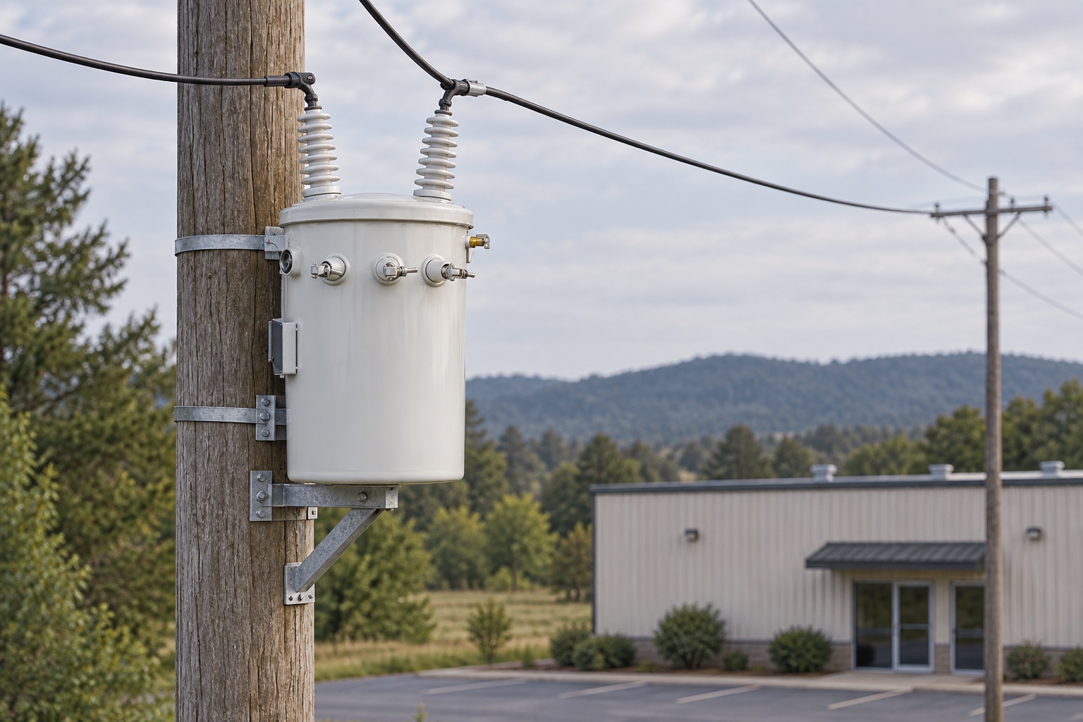
Our single-phase pole-mounted transformer page describes one distribution product category. Confirm its available ratings, terminal configuration, standards, drawings and utility requirements for the specific project rather than extrapolating from a representative image.
What to compare in supplier quotations
Two proposals with the same kVA and nominal voltage are not necessarily equivalent. Compare the complete schedule: frequency, winding connection and taps, impedance, insulation level, temperature rise, cooling, losses, sound requirements, accessories, enclosure and dimensions. Confirm whether quoted values are guaranteed and which tolerances or test documents apply. A lower initial price may not reflect differences in losses, site fit, documentation or required accessories.
Losses are usually separated into no-load (core) and load (winding-related) components under stated test conditions. Their impact depends on the expected load profile and local energy costs; an unloaded transformer still has core loss when energized. Impedance affects voltage drop and fault current, so it must coordinate with the system and protection design. Do not substitute a rule-of-thumb percentage for the manufacturer’s guaranteed data.
For a liquid-filled pole-mounted unit, also clarify fluid type, tank/accessory details, lifting and mounting provisions, primary/secondary terminal arrangement and any utility-specific requirements. For dry-type equipment, room ventilation, enclosure, temperature conditions, sound and fire/building requirements may be decisive. Ask the supplier to mark every deviation from the project schedule rather than treating a brochure range as the offered configuration.
When a unit is installed, keep its approved drawings, nameplate record, routine test report, commissioning results and maintenance history together. Those records make later troubleshooting and replacement comparisons more reliable. Our transformer condition-monitoring overview describes a separate diagnostic topic; it is not a substitute for selecting the correct rating or carrying out required inspections.
How to choose a suitable unit
- Define the supply and load. Record source voltage and frequency, required secondary voltage(s), continuous and intermittent load, power factor, starting or inrush demand, harmonics and expected growth.
- Choose the right capacity. Convert the load to kVA and review peak duty and simultaneous loads. Do not size only from average kW or add an arbitrary margin without checking the operating profile and upstream protection.
- Confirm the connection. State single-phase, winding arrangement, required taps, polarity, neutral/center-tap needs and grounding approach. Ask for the manufacturer’s connection drawing.
- Match the environment. Specify indoor/outdoor location, altitude, ambient temperature, pollution/corrosion exposure, enclosure or mounting, cooling, sound constraints and available space.
- Coordinate protection and installation. Verify fault level, primary and secondary overcurrent protection, surge protection, grounding, isolation, clearances and utility approvals with the responsible engineer and local authority.
- Check documentation and standards. Confirm the requested standard and edition, routine/type test documentation, losses, impedance, temperature rise, insulation level, accessories, warranty and inspection records. Applicable requirements vary by market and project.
For dimensions, capacity ranges and related selection inputs, consult the separate transformer capacity and dimensions guide. That page covers cross-product sizing references; this page focuses on the single-phase principle and the information needed to specify a unit.
Questions to send with an RFQ
- What are the primary and secondary voltages, frequency and required tap range?
- What is the total load in kVA, and are motors, welders, rectifiers or other high-inrush/nonlinear loads included?
- Is the unit liquid-filled or dry-type, pole-mounted, pad-mounted or indoor? What are site conditions and mounting constraints?
- What connection diagram, neutral arrangement, grounding method and terminal/bushing layout are required?
- Which local code, utility specification and product-standard edition apply?
- What protection, accessories, routine test report, drawings, delivery and service documentation are required?

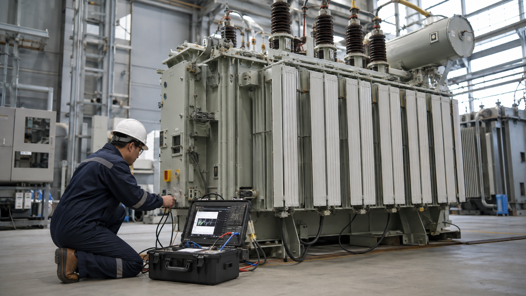
Acceptance checks should compare the delivered nameplate and approved drawings with the order, and review test documents against the contract. The image above does not depict a real test or certify a product. For maintenance planning after installation, see our transformer maintenance guide.
Standards and technical references
Standards are scoped to equipment types and jurisdictions, so specify the required edition and verify applicability with the project engineer. The IEC 60076-1 product page describes general requirements for power transformers and includes single-phase units within its stated scope, subject to its exclusions. IEEE C57.12.90-2021 covers test code methods for liquid-immersed distribution, power and regulating transformers. IEEE C57.12.20-2023 is specifically scoped to overhead-type distribution transformers, single- and three-phase. These references do not determine which rules apply to every country, voltage class or project.
Frequently asked questions
What does a single-phase transformer do?
It transfers AC power between primary and secondary circuits by electromagnetic induction, changing voltage and current according to its winding turns and design. It does not itself convert single-phase power to three-phase.
How do I calculate single-phase transformer current?
Estimate full-load apparent current with I = 1,000 × kVA ÷ volts for the winding being checked. Use the actual winding voltage and nameplate rating; final conductor and protection selection must follow the equipment data and applicable rules.
Is kVA the same as kW?
No. kVA is apparent power. For a sinusoidal load, kW is approximately kVA multiplied by power factor, while transformer current is related to apparent power.
Can a single-phase transformer provide 120/240 V?
Some designs have a center-tapped secondary that can provide two secondary sections and a midpoint when connected as specified. Confirm the exact model diagram; terminal count alone is not enough, and this does not create three-phase power.
How do I select a single-phase transformer?
Start with supply and load voltage, kVA, duty, inrush, frequency, winding arrangement, site environment, protection and required standards. Then confirm the proposal against the approved nameplate data, drawings and local utility or code requirements.
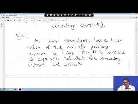
Watch: single-phase transformer fundamentals
This university lecture gives a classroom explanation of the single-phase transformer principle. It is educational background, not a product specification or installation procedure.
Next steps
A reliable selection starts with the load and ends with a verified drawing, nameplate and protection design. Use the formulas here for first-pass estimates; use project-specific data for engineering decisions. If you are evaluating a pole-mounted unit, send the required voltage ratio, frequency, kVA, connection, installation conditions and governing specification with your enquiry so the configuration can be checked directly.