Substation design turns a network requirement into a safe, buildable and operable facility. It coordinates power transformers, switchgear, busbars, protection, control, grounding, structures, foundations, drainage, cables and access. This guide follows the process from design basis and single-line diagram through equipment layout, civil engineering, safety studies, construction interfaces and commissioning.
Define the Substation Design Basis
Start with nominal and maximum voltages, frequency, power transfer, load forecast, source data, fault levels, grounding method, reliability target and grid-code requirements. Record site altitude, temperature, pollution, seismicity, wind, flooding, soil resistivity, available land, transport restrictions and environmental constraints.
The design basis must describe normal, contingency, maintenance and future operating modes. Without agreed scenarios, transformer quantity, bus arrangement, breaker duties and protection philosophy cannot be finalized.
Create the Single-Line Diagram
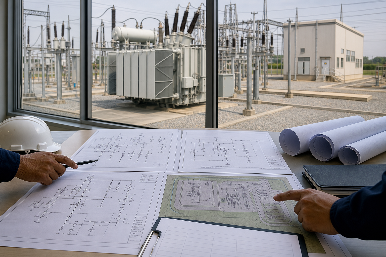
The single-line diagram defines electrical topology: incoming lines, busbars, transformers, breakers, disconnectors, earthing switches, instrument transformers, surge arresters and outgoing feeders. It should show ratings, equipment identifiers, CT/VT ratios, grounding and protection zones.
Common bus schemes include single bus, sectionalized single bus, double bus, ring bus and breaker-and-a-half. More equipment can improve operational flexibility, but it also adds cost, footprint, interlocking and protection complexity.
Quick Comparison and Selection Table
Use this table as a quick review of the main engineering and procurement decisions explained in the article.
| Decision area | Practical meaning | What to verify |
|---|---|---|
| Define the Substation Design Basis | Start with nominal and maximum voltages, frequency, power transfer, load forecast, source data, fault levels, grounding method, reliability target and grid-code requirements. | Record site altitude, temperature, pollution, seismicity, wind, flooding, soil resistivity, available land, transport restrictions and environmental constraints. |
| Create the Single-Line Diagram | The single-line diagram defines electrical topology: incoming lines, busbars, transformers, breakers, disconnectors, earthing switches, instrument transformers, surge arresters and outgoing feeders. | It should show ratings, equipment identifiers, CT/VT ratios, grounding and protection zones. |
| Select Primary Equipment | LBAJI’s 35 kV oil-immersed power transformer can support distribution and renewable substations. | Indoor 40.5 kV-class projects can use KYN61-40.5 metal-clad switchgear , subject to the approved study data. |
| Develop the Substation Layout | The general arrangement locates bays, transformers, control building, cable trenches, roads, fences and future extensions. | Electrical clearances are based on maximum system voltage, insulation level, altitude and standards. |
| AIS vs GIS Layout | Air-insulated substations use open-air clearances and typically need more land. | They offer visible equipment and familiar maintenance. |
Select Primary Equipment
- Power transformers: kVA/MVA, voltage, vector group, impedance, tap range, cooling and losses.
- Circuit breakers: voltage, continuous current, breaking/making current and operating duty.
- Disconnectors and earthing switches: isolation, induced-current duty and interlocking.
- CTs and VTs: ratios, accuracy classes, burdens and insulation levels.
- Surge arresters: system grounding, continuous voltage, energy duty and protective level.
- Busbars and conductors: current, corona, thermal and electrodynamic fault performance.
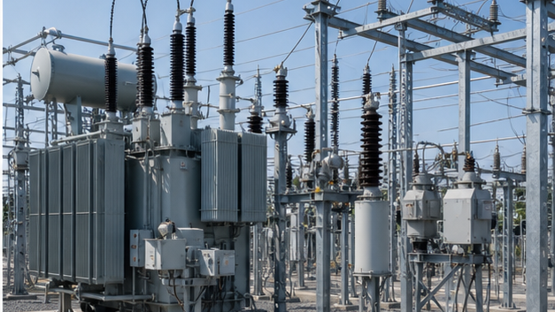
LBAJI’s 35 kV oil-immersed power transformer can support distribution and renewable substations. Indoor 40.5 kV-class projects can use KYN61-40.5 metal-clad switchgear, subject to the approved study data.
Develop the Substation Layout
The general arrangement locates bays, transformers, control building, cable trenches, roads, fences and future extensions. Electrical clearances are based on maximum system voltage, insulation level, altitude and standards. Maintenance and safety clearances must allow removal of breakers, bushings, radiators and transformers.
Arrange traffic so heavy transport can reach transformer foundations without crossing unsafe routes. Provide crane or lifting access, fire separation, oil containment, emergency exits and clear operator movement. Overhead conductors, underground cables, drainage and structures must not conflict.
AIS vs GIS Layout
Air-insulated substations use open-air clearances and typically need more land. They offer visible equipment and familiar maintenance. Gas-insulated substations enclose energized parts in sealed modules, reducing footprint and exposure to pollution. GIS requires building, gas handling, cable and expansion-joint coordination and specialized lifecycle procedures.
Substation Civil and Structural Design
Civil engineering includes grading, foundations, transformer bunds, roads, drainage, trenches, control buildings, fences and fire walls. Geotechnical data determine bearing capacity, settlement and foundation approach. Dynamic loads, short-circuit forces, wind, seismic loads and equipment center of gravity affect structural design.
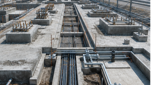
Transformer oil containment must hold the required volume and route water according to environmental rules. Drainage should prevent flooding while controlling contaminated runoff. Cable trenches need slope, sumps, fire stopping, segregation and covers designed for traffic loads.
Substation Earthing Design
The earth grid carries fault and lightning current while limiting touch and step voltage. Design uses soil-resistivity measurements, fault-current split, clearing time, conductor thermal rating, grid geometry, surface layer and bonding. All structures, equipment tanks, fences, cable sheaths and metallic services require coordinated bonding.
A low measured grid resistance alone does not prove safety. Touch, step and transferred potentials must be calculated and then verified by testing after installation.
Protection, Control and SCADA
Protection zones should overlap around lines, buses, transformers and feeders. Typical schemes include line distance or differential, busbar differential, transformer differential, restricted earth fault, overcurrent backup and breaker failure. DC battery systems support tripping, closing, protection and communication during loss of AC auxiliary supply.
Control architecture defines bay controllers, interlocking, event recording, time synchronization, communications, remote commands and cybersecurity. Hardwired safety interlocks should not be casually replaced by communications logic.
Cable and Auxiliary Systems
Separate power, control, communication and sensitive measurement cables where required. Check cable ampacity, voltage drop, short-circuit withstand, routing, bend radius, fire performance and EMC. Station-service AC and DC systems, lighting, HVAC, fire detection and security must remain available under defined contingencies.
3D Substation Design and Coordination
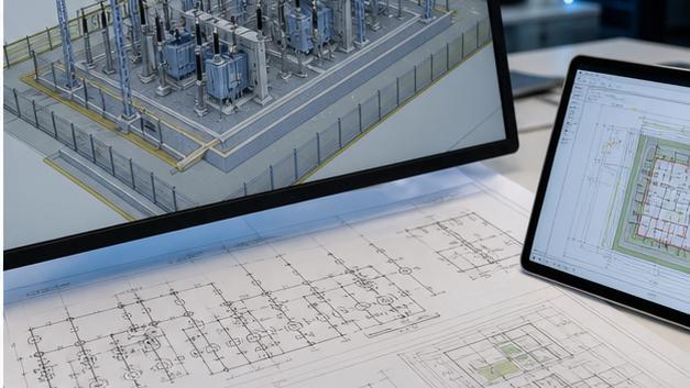
A coordinated 3D model can reveal clashes between structures, conductors, cable trays, foundations and access paths. It also supports clearance checks, material quantities, construction sequencing and maintenance visualization. The model must remain consistent with the single-line diagram, equipment schedules and approved vendor drawings.
Renewable-Energy Substation Design
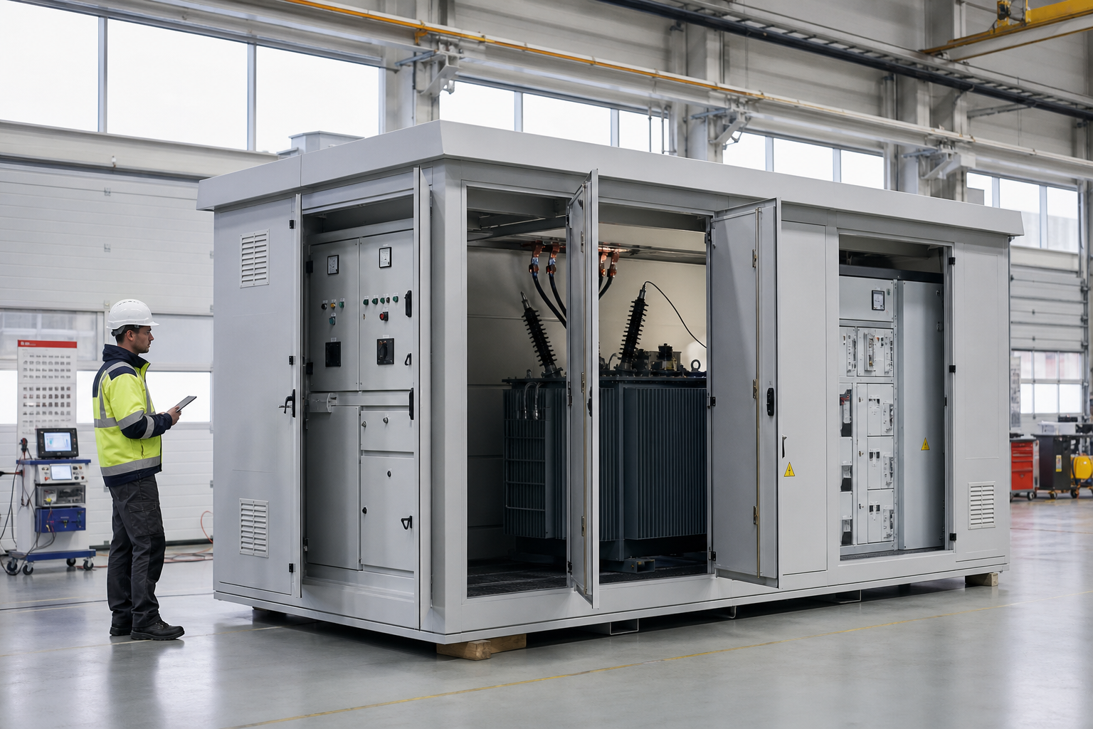
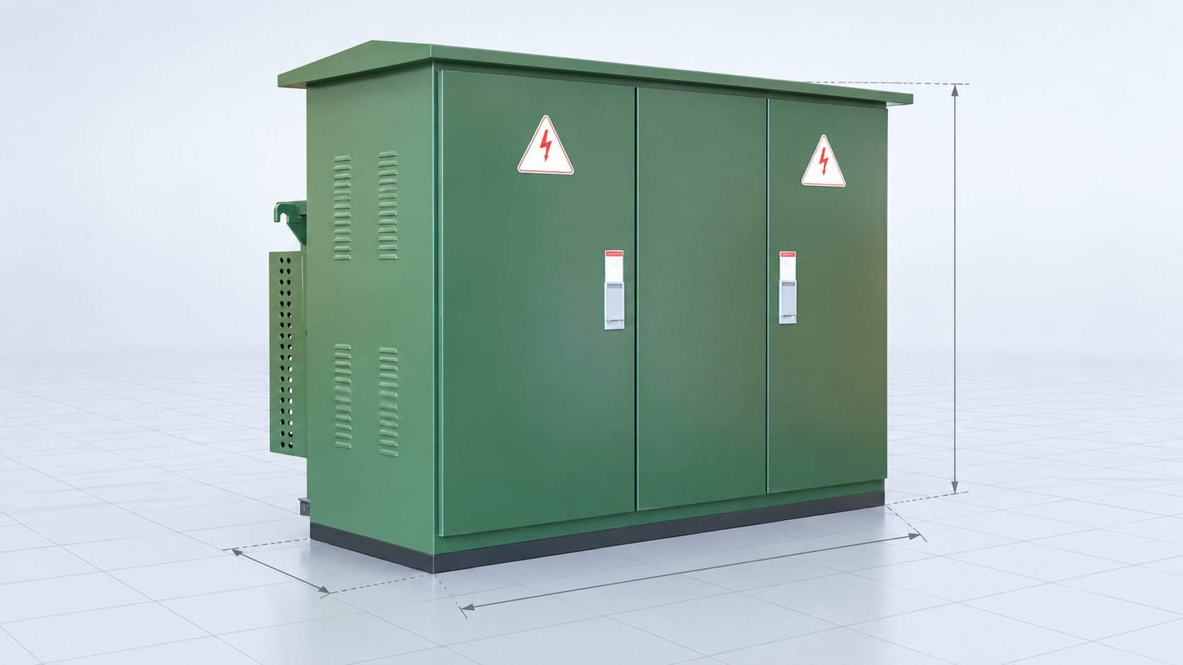
Solar and wind projects add collector circuits, inverter-based behavior, harmonics, reactive-power requirements and grid-code controls. Transformer cyclic loading, cable charging, plant controller interfaces and weak-grid performance may need specialist studies. A 35 kV new-energy box-type substation can package collection transformation, while a photovoltaic AC combiner aggregates inverter outputs upstream.
Design Deliverables
- Design basis and study reports.
- Single-line, protection and metering diagrams.
- General arrangement, sections and clearance drawings.
- Grounding, lightning, lighting and cable layouts.
- Civil, structural, drainage and fire drawings.
- Equipment specifications and data schedules.
- Interlocking, control, SCADA and communication documents.
- Factory tests, site tests and commissioning procedures.
Substation Design Review Checklist
- Confirm all operating and outage scenarios.
- Verify load flow, short circuit and insulation coordination.
- Check equipment ratings against studies.
- Demonstrate protection selectivity and redundancy.
- Verify electrical and maintenance clearances.
- Check earth-grid touch and step voltages.
- Resolve civil, structural and cable interfaces.
- Allow transport, lifting, fire access and future bays.
- Reconcile models, drawings and vendor data.
From site selection to physical layout
Site screening should address network connection, flood level, soil, access, noise, fire exposure, security and future expansion. The physical layout then converts the single-line into safe clearances, equipment bays, cable routes, oil containment, control building interfaces and removal paths.
Why the substation is a network node
A substation is not simply a collection of equipment. Its bus scheme and protection zones determine how faults, maintenance and future expansion affect the wider grid. Reliability studies should test loss of a line, transformer, bus section, DC supply or communications channel before the layout is frozen.
Technical references and further reading
The following independent sources support the standards, terminology, calculations, and safety context discussed in this guide:
- IEEE C37.121 guide for unit substations — IEEE guidance on coordinating incoming, transformer, transition, and outgoing sections in unit substations.
- OSHA electric power transmission and distribution overview — Official safety context for transmission and distribution systems and equipment.
- Electrical substation overview — A general reference for substation functions, types, switching, protection, and transformation.