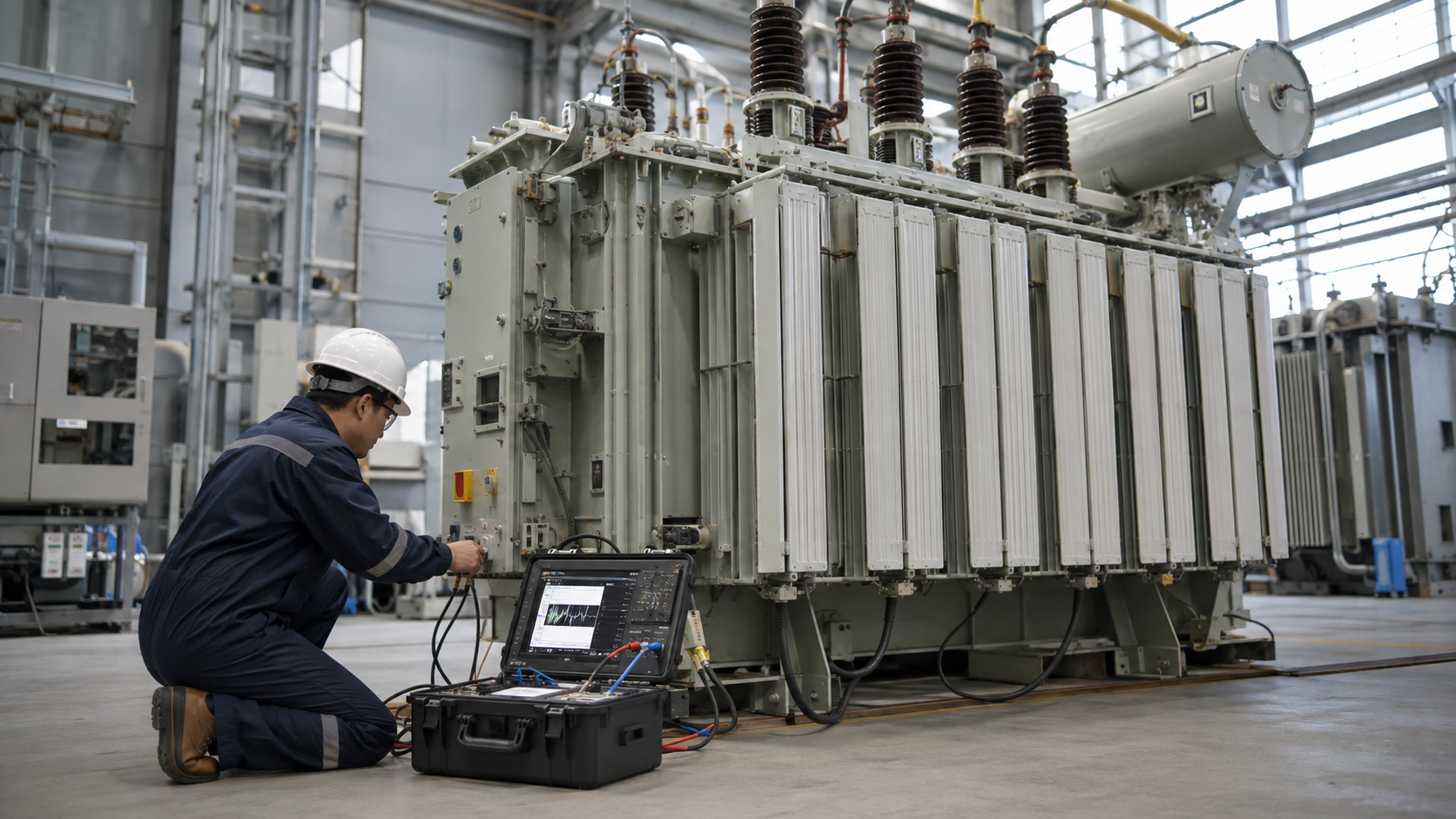
A pole-mounted transformer diagram should distinguish the utility primary circuit, surge arrester and cutout, transformer primary bushing, secondary bushings or terminals, neutral, tank bond, grounding conductor and customer service conductors. Actual utility construction standards vary, and pole equipment is hazardous. Use diagrams for understanding and procurement only; installation, switching and clearances belong to the serving utility and qualified line personnel.
Key Takeaways
- Trace energy from primary conductor through protection to the transformer and service.
- Do not confuse system neutral, tank bonding and grounding-electrode conductors.
- Utility standards control pole framing, clearances and connections.
Reading the Primary Side of the Diagram

The primary conductor supplies the transformer through a fused cutout or other protective device. The cutout provides overcurrent protection and a visible open point under utility procedures. A surge arrester connects between the primary circuit and ground to limit lightning or switching overvoltage.
The lead enters the primary bushing. Single-bushing transformers may use the grounded tank or internal connection as the return in a grounded-wye system; two-bushing units bring both primary terminals out. The nameplate and utility diagram determine the arrangement.
Secondary Bushings, Neutral and Service Conductors
A common North American single-phase distribution unit has two outer secondary terminals and a center tap. The outer-to-outer voltage may be 240 V and each outer-to-center voltage 120 V. The center tap becomes the secondary neutral under the utility grounding design.
Service conductors leave the secondary terminals toward the customer point of connection. Conductor size, service limits, drip loops, connectors and clearances follow utility standards and the applicable code.
Tank Bonding and Grounding Path
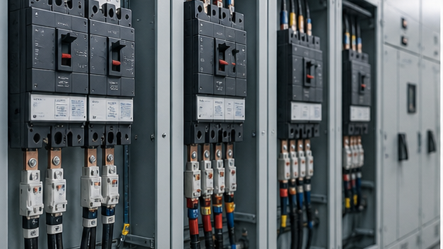
The metal tank, arrester ground and system neutral may be connected to a common grounding conductor under the utility standard. A grounding electrode at the pole helps control potential, but it does not make nearby conductors safe to touch or eliminate step and touch voltage.
A diagram should show electrical bonding separately from physical mounting hardware. Missing or corroded bonds can create dangerous potential and impair surge protection.
Pole-Mounted Transformer Diagram Legend
| Diagram item | Function | Typical location | Verification |
|---|---|---|---|
| Fused cutout | Primary overcurrent protection and isolation point | Pole above transformer | Fuse link, voltage and utility standard |
| Surge arrester | Limits incoming overvoltage | Near primary bushing | Rating, lead length and ground path |
| Primary bushing | Carries primary conductor into tank | Transformer cover | One- or two-bushing design |
| Secondary bushings | Supply service voltage | Tank side or cover | Polarity, voltage and conductor interface |
| Tank/neutral ground | Bonds metal and establishes reference | Tank lug to pole ground | Continuity and utility grounding diagram |
Single-Phase Units and Three-Phase Banks
One transformer commonly serves single-phase loads. Three units can form a bank with delta-delta, delta-wye, grounded-wye or other utility-approved connections. Each bank diagram must show primary and secondary phasing, polarity and neutral treatment.
Open-delta banks use two transformers and provide reduced three-phase capacity. They require engineering review for loading, voltage unbalance, harmonics and protection; they are not created by simply omitting one unit from any three-transformer bank.
Engineering Validation and Safety Boundary
This guide supports specification and procurement; it does not replace a project study, the applicable code, the manufacturer instructions or work by qualified electrical personnel. Verify the following before equipment selection, testing, wiring or energization:
- Treat all pole-mounted equipment as utility-controlled and potentially energized.
- Confirm nameplate polarity, voltage and bushing arrangement before interpreting a diagram.
- Use serving-utility construction standards for clearances and framing.
- Coordinate arrester, cutout and grounding leads with short direct paths.
- Verify bank phasing and rotation before connecting three-phase services.
Information to Include in the RFQ
A useful quotation must be based on the same technical boundary for every supplier. Include the following information and require all deviations to be listed explicitly:
- Primary system voltage, grounding and one- or two-bushing requirement.
- Secondary voltage, phase, center tap or neutral and kVA.
- Pole mounting brackets, lifting, tank dimensions and corrosion finish.
- Bushings, connectors, arrester and cutout scope of supply.
- Utility drawings, losses, impedance, tests and accessories.
From Technical Data to an Approved Decision
Use a staged review rather than approving the first catalogue match. Begin with reading the primary side of the diagram, then reconcile secondary bushings, neutral and service conductors with tank bonding and grounding path. Complete the review with single-phase units and three-phase banks. At each stage, record the source document, units, operating case and person responsible for approval. This prevents a value copied from an old drawing, nominal system label or unrelated product from becoming an uncontrolled design input.
Before acceptance, compare the supplier response line by line with the RFQ and mark every exception. Confirm that drawings, calculations, settings, certificates and test reports refer to the exact offered model and revision. Preserve the approved submittal, nameplate data, factory results and commissioning measurements as the maintenance baseline. If a rating, connection, environment or test condition changes, repeat the affected review rather than assuming the original conclusion remains valid.
Document control should identify revision, approval status and superseded files. Field teams should receive the same approved values used for procurement, while commissioning records should capture any authorized change made during installation. This traceability is especially important when equipment is replaced years later: the next engineer needs verified interfaces and test history, not an incomplete description copied from a purchase order.
Coverage Informed by Current Search Results
The current U.S. Google top-20 review repeatedly surfaced themes including Three Phase Pole Mounted Transformers, Pole Mounted Transformer Diagram, What Is A 15 kVA Pole Mounted Transformer?, Who Are The Leading Pole Mounted Transformer Manufacturers?, Connections. The article addresses those user needs in an original engineering and procurement sequence; competitor brand navigation and unrelated sales material were excluded.
Related LBAJI Resources
Continue with transformer wiring diagram guide electrical transformer guide transformer products. These resources help connect the calculation or component decision to a complete transformer, switchgear, control or distribution specification.
Technical References and Further Reading
- OSHA Electric Power Generation, Transmission and Distribution — Safety requirements for utility electrical work.
- U.S. DOE Distribution Transformers — Distribution transformer resources.
- IEEE Standards Association — Distribution transformer and utility standards.
Conclusion
A useful pole-mounted transformer diagram shows protection, primary and secondary terminals, neutral and grounding as separate functions. The serving utility’s approved construction drawing and nameplate always take precedence over a generic educational sketch.