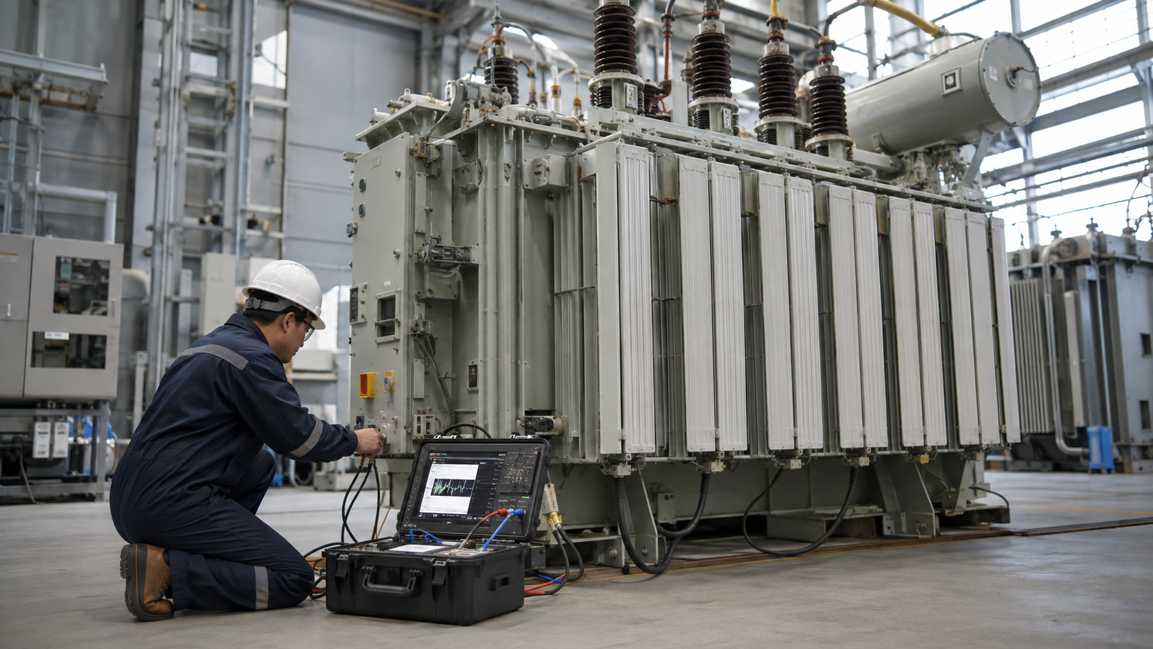
A buck-boost transformer makes a relatively small voltage correction by adding or subtracting a winding voltage, often in an autotransformer connection; it can correct 208 V toward 230/240 V or reduce a slightly high supply, but it normally does not provide isolation. Selection requires input voltage, desired output, phase, load kVA or amperes, connection and continuous duty. A wiring diagram is model- and application-specific and must come from the manufacturer.
Key Takeaways
- Size from voltage difference and load current, not total load kVA alone.
- Autotransformer connections do not provide galvanic isolation.
- Confirm motor voltage range, grounding and exact manufacturer diagram.
How Bucking and Boosting Works
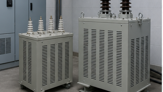
A small secondary winding is connected in series with the supply. With additive polarity, its voltage raises the load voltage; with subtractive polarity, it lowers the load voltage. Reversing the series connection changes boost to buck, but the exact terminals depend on the product diagram.
In an autotransformer connection, part of the power transfers conductively and only the correction portion is transformed magnetically. This allows a small nameplate transformer to support a larger load kVA for a modest voltage change.
Sizing from Load Current and Voltage Difference
The transformed kVA is approximately correction volts × load amperes ÷ 1,000 for single phase. For example, correcting 208 V to 236 V at 40 A requires about 28 × 40 ÷ 1,000 = 1.12 kVA of transformed capacity, subject to the manufacturer selection table and connection.
Do not use the load kVA as the buck-boost nameplate requirement without applying the approved method. Continuous load, motor starting, ambient and enclosure can change the final choice.
Single-Phase and Three-Phase Connections
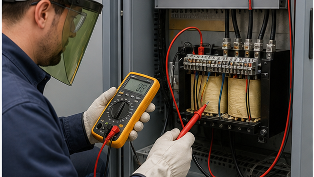
Single-phase applications may use one unit with a series connection. Three-phase correction commonly uses two or three units depending on open-delta or wye arrangements and load conditions. Unequal single-phase loading or four-wire systems require careful neutral and connection review.
The manufacturer diagram specifies primary winding series/parallel links and series-winding polarity. An incorrect link can produce the wrong voltage or a short circuit.
Buck-Boost Selection Examples
| Input | Target | Load current | Correction | Approx. transformed kVA |
|---|---|---|---|---|
| 208 V | 236 V | 40 A | +28 V | 1.12 kVA |
| 208 V | 230 V | 60 A | +22 V | 1.32 kVA |
| 240 V | 220 V | 30 A | −20 V | 0.60 kVA |
| 230 V | 240 V | 50 A | +10 V | 0.50 kVA |
| Note | — | — | — | Use manufacturer tables for final selection |
Application Limits and Alternatives
Buck-boost units are useful when supply voltage is consistently offset by a modest amount. They are not voltage regulators for a widely varying source, and ordinary connections do not correct phase imbalance or waveform problems.
Choose an isolation transformer when galvanic separation, separately derived grounding or larger ratio change is required. Use a regulator, tap-changing transformer or power-electronic solution where voltage changes dynamically.
For a balanced three-phase screening estimate, correcting 480 V to 500 V at 100 A corresponds to about √3 × 20 × 100 ÷ 1,000 = 3.46 kVA of apparent correction. This does not define the size or number of transformer units: the winding arrangement, source wires and manufacturer selection chart decide that. Match the chart against the actual load and exact proposed connection.
For a balanced three-phase screening estimate, correcting 480 V to 500 V at 100 A corresponds to about √3 × 20 × 100 ÷ 1,000 = 3.46 kVA of apparent correction. This does not define the size or number of transformer units: the winding arrangement, source wires and manufacturer selection chart decide that. Match the chart against the actual load and exact proposed connection.
Engineering Validation and Safety Boundary
This guide supports specification and procurement; it does not replace a project study, the applicable code, the manufacturer instructions or work by qualified electrical personnel. Verify the following before equipment selection, testing, wiring or energization:
- Measure worst-case source voltage under representative loading.
- Confirm load voltage tolerance, starting current and continuous duty.
- Verify that lack of isolation is acceptable for grounding and safety.
- Use only the exact manufacturer wiring diagram for the selected model.
- Check overcurrent protection, conductor ampacity and enclosure environment.
Information to Include in the RFQ
A useful quotation must be based on the same technical boundary for every supplier. Include the following information and require all deviations to be listed explicitly:
- Measured minimum/maximum input and required output voltage.
- Phase, frequency, load amperes/kVA and motor-starting duty.
- Required buck or boost amount and acceptable regulation.
- Grounding, neutral, isolation and enclosure requirements.
- Connection diagram, taps, protection, dimensions and test data.
From Technical Data to an Approved Decision
Use a staged review rather than approving the first catalogue match. Begin with how bucking and boosting works, then reconcile sizing from load current and voltage difference with single-phase and three-phase connections. Complete the review with application limits and alternatives. At each stage, record the source document, units, operating case and person responsible for approval. This prevents a value copied from an old drawing, nominal system label or unrelated product from becoming an uncontrolled design input.
Before acceptance, compare the supplier response line by line with the RFQ and mark every exception. Confirm that drawings, calculations, settings, certificates and test reports refer to the exact offered model and revision. Preserve the approved submittal, nameplate data, factory results and commissioning measurements as the maintenance baseline. If a rating, connection, environment or test condition changes, repeat the affected review rather than assuming the original conclusion remains valid.
Document control should identify revision, approval status and superseded files. Field teams should receive the same approved values used for procurement, while commissioning records should capture any authorized change made during installation. This traceability is especially important when equipment is replaced years later: the next engineer needs verified interfaces and test history, not an incomplete description copied from a purchase order.
Buck-Boost, Isolation Transformer or Voltage Regulator?
| Project need | Typical solution to evaluate | Key limit to confirm |
|---|---|---|
| A stable, modest voltage correction | Buck-boost transformer in the approved connection | It generally follows source-voltage variation and an autotransformer connection does not isolate the load. |
| Electrical separation or a separately derived secondary | Isolation transformer designed for the application | Grounding, shielding, insulation and protection still require project review. |
| Input voltage that varies during operation | Voltage regulator or another dynamic correction method | A fixed buck-boost ratio does not hold output constant as the input changes. |
Related LBAJI Resources
For the basic magnetic principle, read our transformer fundamentals guide. Review the transformer wiring and diagram guide for connection checks, and use the transformer sizing calculation guide when selecting equipment for a full load schedule. Related references include the step-up transformer guide, transformer calculator and transformer product range.
Frequently Asked Questions
Can a buck-boost transformer change 208 V to 240 V?
A correctly selected unit may make that correction, subject to load, phase and manufacturer connection data.
Does buck-boost provide isolation?
Not when connected as an autotransformer; primary and load are electrically connected.
Why is its nameplate kVA smaller than load kVA?
Only the correction voltage portion of the power is magnetically transformed.
Can it stabilize fluctuating voltage?
It provides a fixed correction and is not a dynamic regulator.
Can one unit serve a three-phase load?
Three-phase arrangements generally require two or three units using approved diagrams.
Technical References
Manufacturer selection charts and connection instructions apply to specific product families. Use them to check the exact voltage combination and wiring diagram for the offered model.
Conclusion
Buck-boost transformers are efficient fixed voltage-correction tools when the source, target and load are well defined. Calculate transformed kVA, confirm the non-isolated grounding arrangement and follow the exact manufacturer connection diagram.