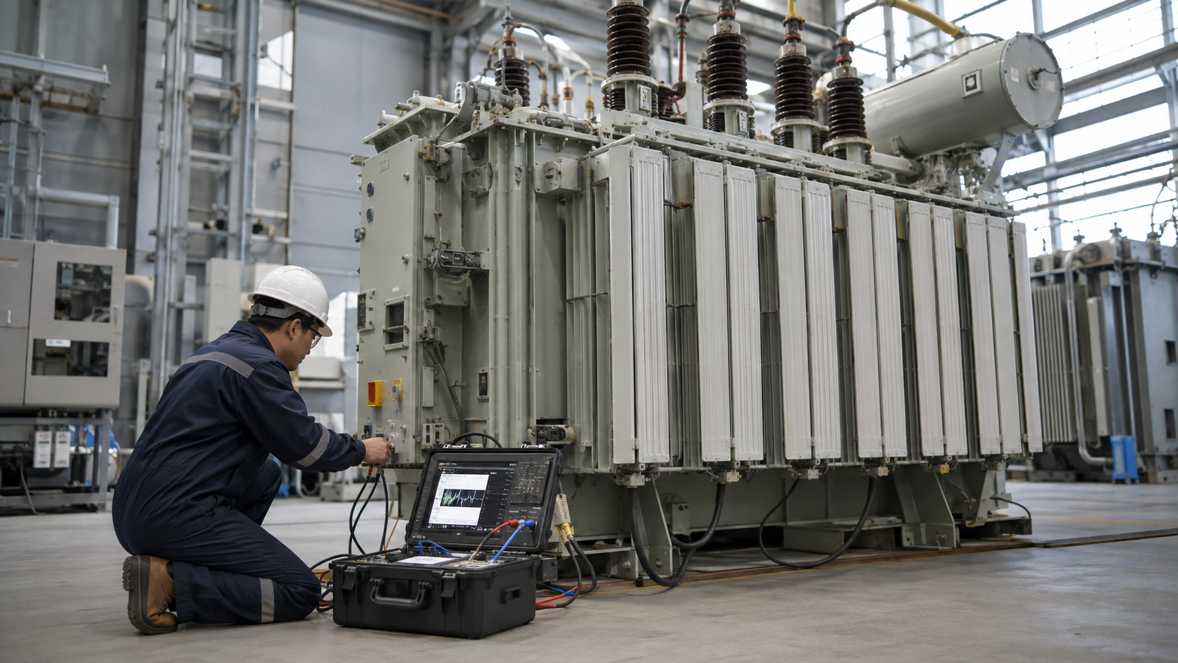
Three-phase transformer calculations use kVA = √3 × line voltage × line current ÷ 1,000 and I = kVA × 1,000 ÷ (√3 × line voltage); ratio, impedance, voltage drop and fault current require additional transformer data. Use line-to-line voltage in the balanced three-phase formula and distinguish line from phase quantities for delta and wye windings. Calculation results guide design but do not replace code sizing or studies.
Key Takeaways
- Use √3 with line voltage and line current.
- Delta and wye phase values differ even when line values are known.
- Impedance controls regulation and available secondary fault current.
kVA and Full-Load Current

For balanced three phase, kVA = 1.732 × VLL × IL ÷ 1,000. A 480 V system at 120 A is about 99.8 kVA. Rearranging, a 150 kVA transformer at 480 V carries about 180.4 A; at 208 V it carries about 416.4 A.
These are nameplate full-load currents. Conductor and breaker sizes require continuous-load, terminal, ambient, inrush and code checks.
Delta and Wye Phase Quantities
In wye, phase voltage is line voltage ÷ √3 and phase current equals line current. In delta, phase voltage equals line voltage and phase current is line current ÷ √3. Use these relationships when checking winding turns or individual coil current.
A 480 V delta winding sees 480 V per phase; a 208Y/120 V winding sees 120 V per phase. That is why line-voltage ratio alone does not equal individual coil turns ratio for delta-wye. Commercial labels such as “dry-type triplex” need separate confirmation from the manufacturer’s winding diagram; our dry-type triplex guide explains what to verify.
Ratio, Regulation and Voltage Drop

The ideal phase-voltage ratio equals turns ratio. Loaded secondary voltage changes because of winding resistance and leakage reactance. Percent regulation depends on impedance, load current and power factor.
Feeder voltage drop is separate from transformer regulation. Model both when checking motor starting or distant loads, using actual conductor and transformer data.
Three-Phase Calculation Examples
| Calculation | Inputs | Formula | Result |
|---|---|---|---|
| Load kVA | 480 V, 120 A | 1.732 × 480 × 120 ÷ 1,000 | 99.8 kVA |
| 150 kVA current | 480 V | 150,000 ÷ (1.732 × 480) | 180.4 A |
| 150 kVA current | 208 V | 150,000 ÷ (1.732 × 208) | 416.4 A |
| Wye phase voltage | 208 V line | 208 ÷ 1.732 | 120 V |
| Fault estimate | 1,203 A, 5.75% Z | 1,203 ÷ 0.0575 | 20.9 kA |
Impedance and Fault Current Estimate
A rough secondary terminal fault-current estimate with a stiff source is full-load current ÷ per-unit impedance. A 1,000 kVA, 480 V transformer has about 1,203 A full-load current; at 5.75% impedance, the idealized terminal fault current is about 20.9 kA.
Real studies include source impedance, cables, motors, tolerances, tap position and X/R ratio. Do not use the simple estimate as a final equipment-duty study.
Engineering Validation and Safety Boundary
This guide supports specification and procurement; it does not replace a project study, the applicable code, the manufacturer instructions or work by qualified electrical personnel. Verify the following before equipment selection, testing, wiring or energization:
- Confirm line-to-line voltage and balanced three-phase assumptions.
- Apply delta/wye relationships before using winding quantities.
- Use nameplate impedance and its tolerance.
- Include source, cable and motor contribution in final fault studies.
- Separate calculation current from code equipment sizing.
Information to Include in the RFQ
A useful quotation must be based on the same technical boundary for every supplier. Include the following information and require all deviations to be listed explicitly:
- kVA, line voltages, phase, frequency and vector group.
- Impedance, taps, regulation and source fault data.
- Load current, power factor, motors and harmonics.
- Ambient, altitude, cooling and future growth.
- Required studies, calculations, tests and guaranteed values.
From Technical Data to an Approved Decision
Use a staged review rather than approving the first catalogue match. Begin with kva and full-load current, then reconcile delta and wye phase quantities with ratio, regulation and voltage drop. Complete the review with impedance and fault current estimate. At each stage, record the source document, units, operating case and person responsible for approval. This prevents a value copied from an old drawing, nominal system label or unrelated product from becoming an uncontrolled design input.
Before acceptance, compare the supplier response line by line with the RFQ and mark every exception. Confirm that drawings, calculations, settings, certificates and test reports refer to the exact offered model and revision. Preserve the approved submittal, nameplate data, factory results and commissioning measurements as the maintenance baseline. If a rating, connection, environment or test condition changes, repeat the affected review rather than assuming the original conclusion remains valid.
Document control should identify revision, approval status and superseded files. Field teams should receive the same approved values used for procurement, while commissioning records should capture any authorized change made during installation. This traceability is especially important when equipment is replaced years later: the next engineer needs verified interfaces and test history, not an incomplete description copied from a purchase order.
Coverage Informed by Current Search Results
The current U.S. Google top-20 review repeatedly surfaced themes including Three Phase kVA Formula, HOW TO SIZE A TRANSFORMER, What is the formula for sizing a 3-phase transformer with single-phase loads?, How does delta connection affect transformer sizing?, Table 1. The article addresses those user needs in an original engineering and procurement sequence; competitor brand navigation and unrelated sales material were excluded.
Related LBAJI Resources
Continue with transformer calculations guide amps to kVA guide transformer calculator. These resources help connect the calculation or component decision to a complete transformer, switchgear, control or distribution specification.
Technical References and Further Reading
- IEC 60076-1 — Transformer ratings and impedance data.
- NIST SI Units — Electrical units.
- NFPA Codes and Standards — Installation and protection requirements.
Conclusion
Three-phase calculations are reliable when line, phase, connection and impedance quantities are kept distinct. Use the formulas for transparent checks, then complete regulation, fault, protection and code studies with verified system data.