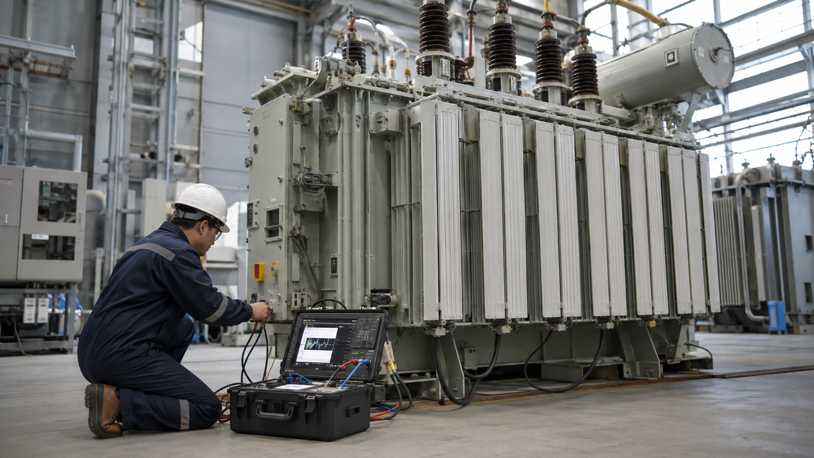
A railway transformer adapts utility or onboard power for traction and auxiliary loads; its design is shaped by repeated overload, harmonics, vibration, restricted clearances, earthing, electromagnetic compatibility, fire behavior, and high availability.
Key Takeaways
- Identify the exact duty and system boundary before selecting equipment.
- Verify ratings, protection, environment, interfaces, and maintainability together.
- Use qualified personnel and project-specific standards for final decisions.
Quick Selection Table
| Decision area | Practical meaning | Project check |
|---|---|---|
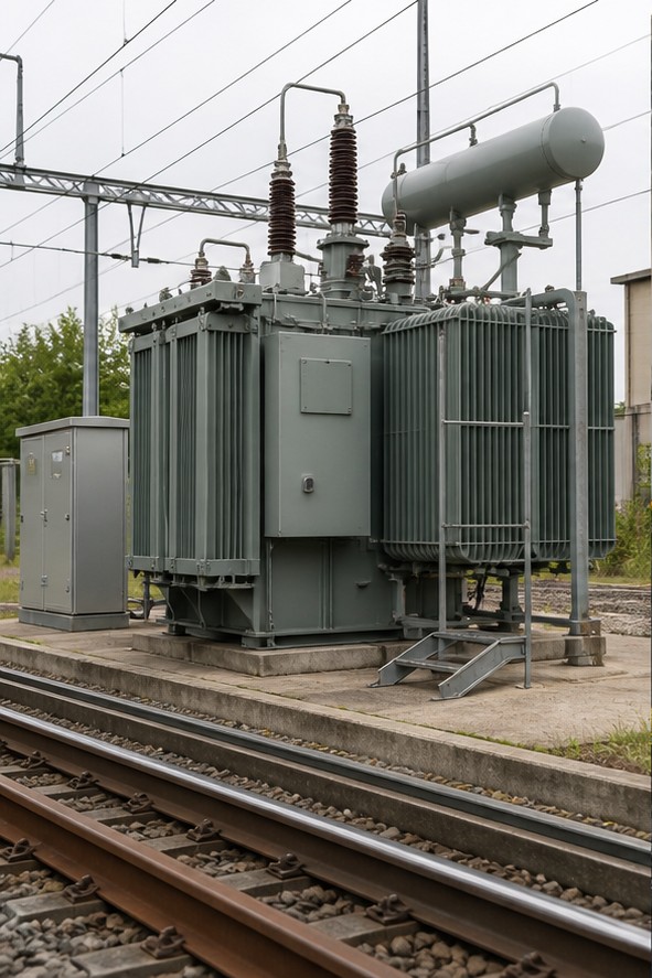
| Traction substation transformers | Wayside traction transformers convert grid voltage to the railway feeding system. | Verify drawings, ratings, interfaces, environment, protection, and acceptance evidence. |
| Onboard traction transformers | On electric locomotives and multiple units, the main transformer feeds converters and auxiliary circuits. | Verify drawings, ratings, interfaces, environment, protection, and acceptance evidence. |
| Auxiliary and station transformers | Smaller units supply signaling, points, communications, lighting, ventilation, depots, stations, and control systems. | Verify drawings, ratings, interfaces, environment, protection, and acceptance evidence. |
| Load cycle and thermal design | Use train headway, vehicle power, acceleration, gradient, regeneration, diversity, contingency operation, and future traffic. | Verify drawings, ratings, interfaces, environment, protection, and acceptance evidence. |
| Harmonics and converter interaction | Power-electronic converters create harmonic current and voltage distortion. | Verify drawings, ratings, interfaces, environment, protection, and acceptance evidence. |
| Insulation, earthing, and protection | Coordinate lightning and switching impulse levels, clearances, neutral treatment, return current, rail potential, surge arresters, differential protection, overcurrent, thermal devices, pressure or gas protection, and fire containment. | Verify drawings, ratings, interfaces, environment, protection, and acceptance evidence. |
Traction substation transformers
Wayside traction transformers convert grid voltage to the railway feeding system. Duty depends on AC or DC traction, feeding arrangement, short-circuit level, timetable, regeneration, redundancy, and utility interface. Load is highly time-varying rather than a steady industrial profile.
Record the assumptions behind every rating. Nameplate values, the one-line diagram, cable schedule, protection study, ambient conditions, and operating history should agree before a decision is approved. If they do not, stop and resolve the discrepancy rather than choosing a component from a catalogue description.
Onboard traction transformers
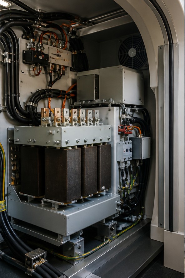
On electric locomotives and multiple units, the main transformer feeds converters and auxiliary circuits. Mass, dimensions, cooling, vibration, acoustic limits, fire behavior, and roof or underfloor integration are as important as MVA and voltage.
Treat safety as a design input. Isolation, lockout/tagout, verification of absence of voltage, grounding, stored-energy control, approach boundaries, and suitable personal protective equipment must follow the site procedure and applicable law. Only qualified personnel should open, test, connect, or lift energized-power equipment.
Auxiliary and station transformers
Smaller units supply signaling, points, communications, lighting, ventilation, depots, stations, and control systems. Critical loads may require independent feeders, UPS systems, generators, or redundant transformers with coordinated transfer logic.
For procurement, state the required standard, ratings, environment, interfaces, routine tests, drawings, certificates, spare parts, and acceptance criteria. Ask suppliers to list deviations explicitly. Comparable bids are possible only when every bidder is answering the same technical requirement.
Load cycle and thermal design
Use train headway, vehicle power, acceleration, gradient, regeneration, diversity, contingency operation, and future traffic. Thermal modeling should cover peaks and recovery periods. A simple average kW can hide damaging repeated overload.
For maintenance, establish a clean baseline at commissioning and trend condition rather than relying on one isolated measurement. Photographs, torque records, insulation results, thermography, event logs, and oil or component tests can reveal change before it becomes an outage.
Harmonics and converter interaction
Power-electronic converters create harmonic current and voltage distortion. Specify harmonic spectrum, losses, winding arrangement, shielding, filters, resonance studies, and temperature limits. Verify compatibility with protection, signaling, and communications.
Record the assumptions behind every rating. Nameplate values, the one-line diagram, cable schedule, protection study, ambient conditions, and operating history should agree before a decision is approved. If they do not, stop and resolve the discrepancy rather than choosing a component from a catalogue description.

Insulation, earthing, and protection
Coordinate lightning and switching impulse levels, clearances, neutral treatment, return current, rail potential, surge arresters, differential protection, overcurrent, thermal devices, pressure or gas protection, and fire containment.
Treat safety as a design input. Isolation, lockout/tagout, verification of absence of voltage, grounding, stored-energy control, approach boundaries, and suitable personal protective equipment must follow the site procedure and applicable law. Only qualified personnel should open, test, connect, or lift energized-power equipment.
Mechanical and environmental duty
Apply vibration and shock, tunnel or coastal pollution, altitude, temperature, snow, dust, salt, vandalism, transport loads, noise, and restricted maintenance access. Terminals and coolers need protection without obstructing service.
For procurement, state the required standard, ratings, environment, interfaces, routine tests, drawings, certificates, spare parts, and acceptance criteria. Ask suppliers to list deviations explicitly. Comparable bids are possible only when every bidder is answering the same technical requirement.
Procurement and acceptance
Provide network data, traction load cycle, overload profile, converter harmonics, earthing, interfaces, losses, sound, dimensions, mass, fire requirements, tests, spares, monitoring, reliability targets, and documentation. Include factory and site acceptance plans.
For maintenance, establish a clean baseline at commissioning and trend condition rather than relying on one isolated measurement. Photographs, torque records, insulation results, thermography, event logs, and oil or component tests can reveal change before it becomes an outage.
Practical Specification Workflow
- Define normal, abnormal, and contingency operating cases.
- Collect verified system and nameplate data.
- Select the governing codes and standards.
- Calculate continuous, short-time, and fault duties.
- Coordinate protection, isolation, grounding, and controls.
- Check environment, layout, transport, installation, and service access.
- Issue drawings, tests, documentation, and acceptance criteria.
- Review deviations before placing the order.
How to Review a Supplier Submittal
Begin with a compliance matrix instead of a brochure. Check every requested rating and interface against the supplier drawing, data sheet, calculation, and test plan. Confirm that stated values apply to the offered configuration, enclosure, ambient temperature, altitude, and accessories. Resolve exclusions involving protection, terminals, controls, monitoring, installation, commissioning, and spare parts before approval. Where a standard permits alternatives, record which option has been supplied.
Next, test the proposal against credible operating events: maximum and minimum voltage, peak load, starting or energization, external fault, loss of cooling, maintenance isolation, communication failure, and the planned contingency. Confirm access for inspection and component replacement. Require final as-built drawings, nameplate schedules, routine-test reports, settings, manuals, and a clear warranty contact. This review prevents a technically plausible product from arriving with the wrong interfaces or incomplete scope.
Related LBAJI Resources
Review the relevant LBAJI equipment page, the main technical guide, and the related articles on system selection and safety and installation or application planning. For a quotation, provide the one-line diagram, ratings, quantity, environment, and required standards.
Educational Video
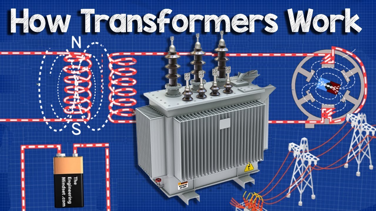
This independent video provides useful visual background for the equipment and electrical principles discussed above.
Frequently Asked Questions
Is this equipment safe to work on while energized?
No general article can authorize energized work. De-energize whenever feasible and follow the site electrical-safety program, risk assessment, and qualified-person requirements.
Which nameplate data should be recorded first?
Record manufacturer, model, serial number, voltage, phase, frequency, current or kVA, insulation or interrupting ratings, connection, cooling, and all accessory data relevant to the application.
Can a replacement be chosen from dimensions alone?
No. Mechanical fit does not prove electrical, thermal, protective, environmental, or interface compatibility.
What should be included in a supplier quotation?
Require ratings, standards, drawings, deviations, routine tests, documentation, warranty, lead time, spares, and site or commissioning scope.
Who should approve the final design?
A qualified engineer and the responsible owner, utility, authority, or safety organization should approve the design according to the jurisdiction and project scope.
Technical References
Conclusion
A railway transformer adapts utility or onboard power for traction and auxiliary loads; its design is shaped by repeated overload, harmonics, vibration, restricted clearances, earthing, electromagnetic compatibility, fire behavior, and high availability. Final selection, installation, testing, and maintenance must be based on project data and approved procedures rather than a general web guide.