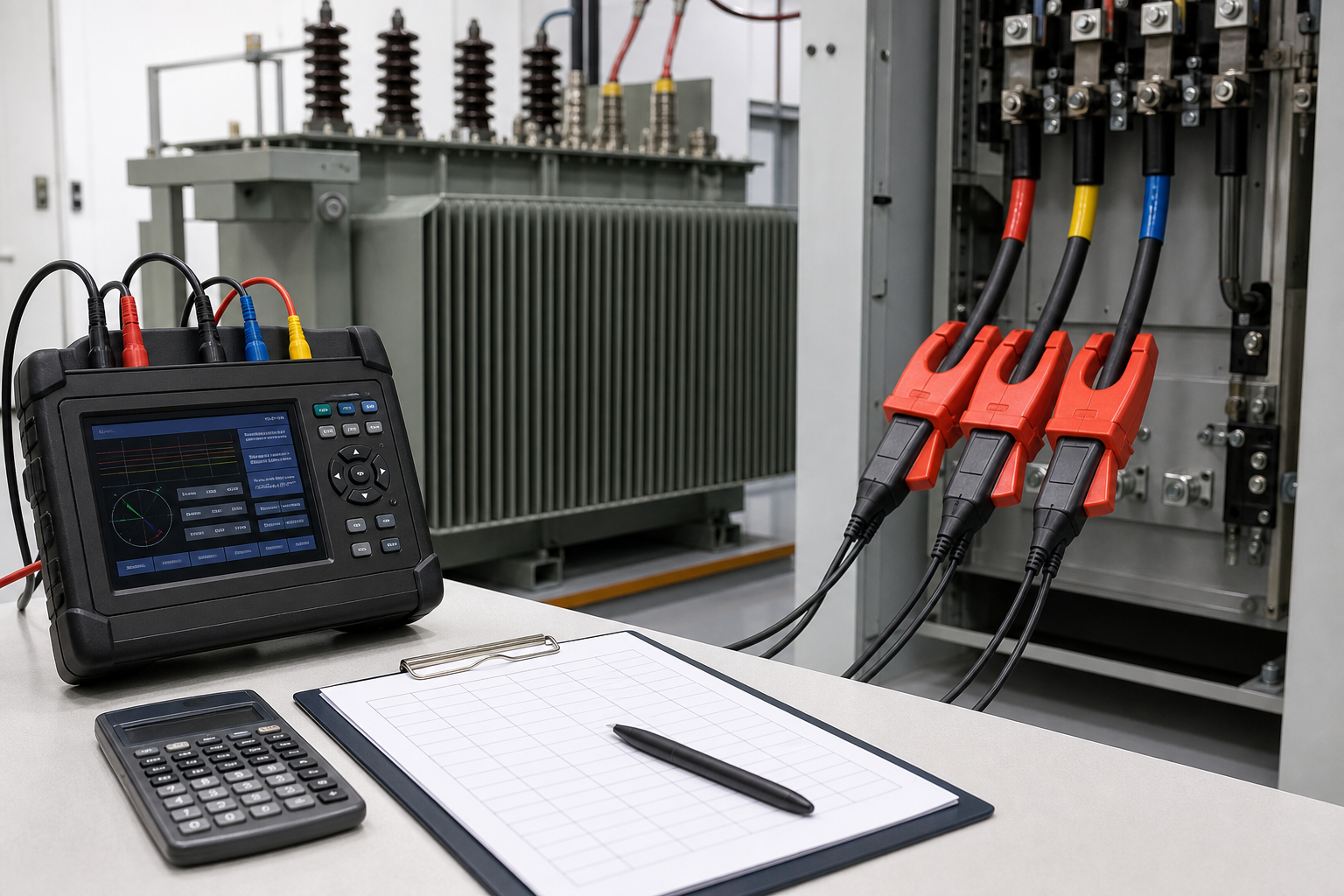
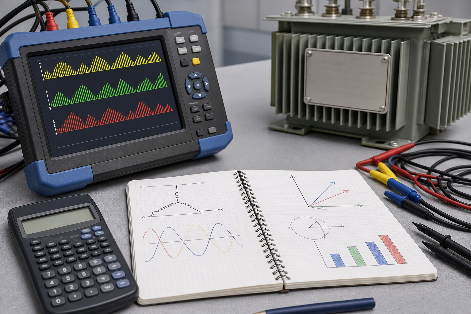
An electrical distribution system transfers power from a utility connection or generator through substations, transformers, switchgear, panels and cables to the final loads. Good design delivers acceptable voltage, clears faults selectively, supports maintenance and allows expansion without unnecessary cost. This guide presents a practical power distribution system design process for industrial, commercial and renewable-energy projects.
Start With the System Requirements
Before selecting equipment, define the incoming supply, load profile, reliability target, operating philosophy and environment. Record nominal and maximum voltage, frequency, utility fault level, grounding method, available capacity, tariff constraints and connection rules. Identify critical loads, permitted outage duration, motor starting, harmonic sources, future expansion and any generator or energy-storage interface.
A design basis should also name the governing electrical, equipment, fire and safety standards. This prevents later conflict between cable rules, switchgear construction, protection settings and installation practice.
Build an Accurate Load Schedule
List each load with rated kW or kVA, voltage, phase, efficiency, power factor, starting method, duty and criticality. Apply documented demand and diversity factors by load group rather than one arbitrary percentage. Separate continuous, intermittent, standby and future loads.
The load schedule determines transformer capacity and feeder current, but it must also support operating scenarios. Check normal utility supply, transformer outage, generator operation, bus-coupler transfer, maintenance and future stages. Large motors require voltage-drop and starting studies, not just steady-state current.
Quick Comparison and Selection Table
Use this table as a quick review of the main engineering and procurement decisions explained in the article.
| Decision area | Practical meaning | What to verify |
|---|---|---|
| Start With the System Requirements | Before selecting equipment, define the incoming supply, load profile, reliability target, operating philosophy and environment. | Record nominal and maximum voltage, frequency, utility fault level, grounding method, available capacity, tariff constraints and connection rules. |
| Build an Accurate Load Schedule | List each load with rated kW or kVA, voltage, phase, efficiency, power factor, starting method, duty and criticality. | Apply documented demand and diversity factors by load group rather than one arbitrary percentage. |
| Choose Distribution Voltage Levels | Higher distribution voltage reduces current, cable size and voltage drop for large or remote loads, but increases equipment cost and technical requirements. | Medium-voltage electrical distribution is often efficient for large campuses, factories, mines and renewable sites. |
| Select the Network Topology | A radial feeder has one normal source path. | It is simple and economical but a feeder fault interrupts downstream loads until isolation and repair. |
| Transformer Selection | Choose transformer kVA from calculated demand, motor starting, harmonic heating, ambient conditions, redundancy and future capacity. | Define primary and secondary voltage, tap range, vector group, impedance, losses, cooling, insulation, noise and accessories. |
Choose Distribution Voltage Levels
Higher distribution voltage reduces current, cable size and voltage drop for large or remote loads, but increases equipment cost and technical requirements. Medium-voltage electrical distribution is often efficient for large campuses, factories, mines and renewable sites. Low-voltage distribution is appropriate near final utilization loads.
Transformer locations should balance MV cable length against LV current and cable quantity. Several distributed transformers can reduce LV losses and voltage drop, while a centralized arrangement may simplify operation and spares.
Select the Network Topology
Radial distribution
A radial feeder has one normal source path. It is simple and economical but a feeder fault interrupts downstream loads until isolation and repair.
Ring or loop distribution
A ring provides two possible supply directions. It improves restoration but requires sectionalizing devices, interlocks and protection suited to the operating mode. Compact ring networks can use equipment such as the LBHB-12 gas-insulated ring main unit.
Double-ended and sectionalized buses
Two sources feed separate bus sections with a bus coupler. The coupler may be normally open or closed depending on source capacity, fault level and protection. Automatic transfer must prevent unintended paralleling unless the system is designed for it.
Transformer Selection
Choose transformer kVA from calculated demand, motor starting, harmonic heating, ambient conditions, redundancy and future capacity. Define primary and secondary voltage, tap range, vector group, impedance, losses, cooling, insulation, noise and accessories. Transformer impedance strongly affects secondary fault current and voltage regulation.
LBAJI’s 35 kV oil-immersed transformer supports higher-voltage distribution, while a YBM-12 prefabricated substation integrates MV switching, transformer and LV distribution in a compact package.
Short-Circuit and Equipment Rating
Calculate maximum fault current at every bus to select breaker interrupting capacity, busbar withstand, CT duty and cable short-circuit rating. Also calculate minimum fault current so relays and protective devices remain sensitive at remote ends. Consider utility contribution, generators, motors, transformer impedance and operating configurations.
Equipment ratings must exceed the prospective duty with the correct duration and standard. Do not compare a breaker breaking rating directly with a busbar short-time withstand rating; they describe different functions.
Protection Coordination
The protective device closest to a fault should normally clear it while healthy sections remain energized. A coordination study reviews time-current curves, instantaneous elements, transformer inrush, motor starting, cable damage curves and equipment withstand. Differential, earth-fault, directional and breaker-failure functions may be required at higher voltage or for critical assets.
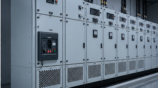
Medium-voltage systems can use KYN28A-12 withdrawable switchgear. For 40.5 kV-class applications, see KYN61-40.5 switchgear. Final relay and CT selection must follow the fault and coordination studies.
Low-Voltage Distribution Design
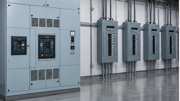
Low-voltage switchboards distribute high secondary current through main, tie and feeder breakers. Verify busbar current, temperature rise, short-circuit withstand, form of separation, ingress rating and arc mitigation. Downstream panels require correctly rated incomers, branch protection, neutral and protective-earth bars, spare ways and clear circuit identification.
Cable Sizing and Voltage Drop
Cable selection must satisfy load current after installation correction factors, protective-device coordination, voltage drop, short-circuit thermal withstand and mechanical/environmental conditions. Grouping, ambient temperature, soil thermal resistivity, burial depth and harmonics can reduce ampacity. Neutral conductors may need special attention with triplen harmonics from nonlinear single-phase loads.
Grounding and Earthing
System grounding controls fault current and transient overvoltage. Equipment earthing bonds exposed conductive parts and supports rapid protective operation. Design includes transformer neutral treatment, earth electrodes or grid, protective conductors, bonding, touch/step voltage and lightning protection. Ground-fault protection settings must match the chosen grounding method.
Reliability, Maintainability and Safety
Reliability is not simply adding a second source. Confirm that each source, transformer and bus section can carry the required emergency load and that common-mode failures are controlled. Provide safe isolation points, earthing switches, interlocks, access clearances and maintainable equipment. Arc-flash analysis, remote operation and arc-resistant construction may reduce risk.
Design Documentation and Studies
The single-line diagram is the system’s master map. It should agree with load schedules, cable schedules, equipment data, protection drawings and operating procedures. Required studies commonly include load flow, short circuit, coordination, arc flash, motor starting, grounding and harmonic analysis.
Design Review Checklist
- Confirm all operating modes and source capacities.
- Reconcile load schedule totals with transformer and generator ratings.
- Verify voltage drop and motor-starting performance.
- Check maximum and minimum fault current at every bus.
- Confirm equipment interrupting and withstand ratings.
- Demonstrate protection selectivity and equipment protection.
- Review grounding, touch/step voltage and surge protection.
- Check cable routes, bending space, heat dissipation and access.
- Define factory acceptance, site acceptance and commissioning tests.
From generation to the final load
An electrical distribution system links the utility or generator to transformers, switchgear, main boards, feeders, panels and utilization equipment. Each voltage transformation trades current against insulation and equipment cost. The topology must also provide a defined fault path and allow the smallest practical section to be isolated.
Modern distribution systems and distributed energy
PV, batteries, generators and controllable loads can create bidirectional power flow and changing fault contribution. Protection, anti-islanding, metering, grounding and operating procedures must cover every source configuration. Digital meters and automation improve visibility, but the underlying one-line model and settings must remain accurate.
Technical references and further reading
The following independent sources support the standards, terminology, calculations, and safety context discussed in this guide:
- NIST SI units for electric current — Authoritative definitions and relationships for amperes, volts, watts, and ohms.
- NIST Guide to SI electrical conversion factors — Official conversion factors for electricity, magnetism, energy, and related quantities.
- OSHA electrical safety requirements — Safety context for applying electrical calculations to transmission and distribution work.