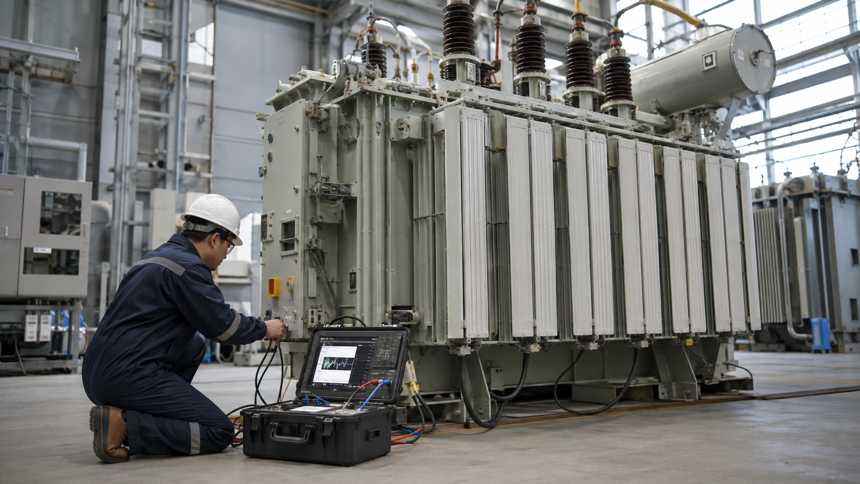
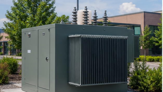
A pad-mounted transformer is a ground-level, tamper-resistant distribution transformer connected to underground primary and secondary cables; selection covers radial or loop feed, dead-front or live-front interfaces, kVA, voltage, fusing, grounding, enclosure and utility requirements. The concrete pad, clearances, bollards, cable windows, drainage and working space are part of the installation. Utility-approved drawings and qualified personnel control medium-voltage work.
Key Takeaways
- Match feed arrangement and cable interfaces to the utility system.
- Size from diversified load, motors and future capacity.
- Coordinate transformer, pad, cables, protection and site access together.
Radial and Loop-Feed Arrangements
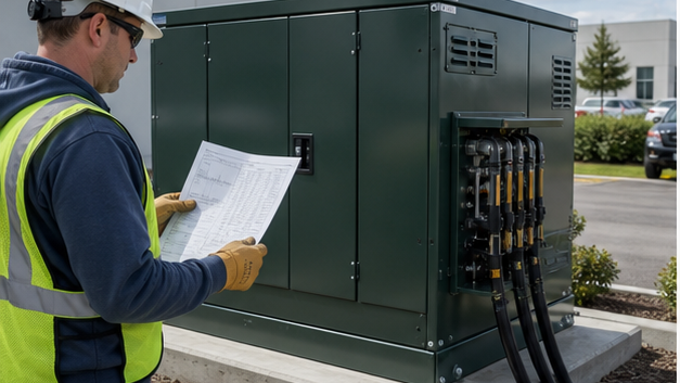
A radial-feed transformer has one incoming primary source path. Loop-feed units provide two cable paths and switching points so the utility can sectionalize or reconfigure a loop. Loop capability does not automatically provide uninterrupted service; operating practice and network design determine restoration.
Specify bushing wells, inserts, parking stands, switches and phasing to the serving utility standard. Cable ratings and terminations must match system voltage, conductor and fault duty.
Dead-Front, Live-Front and Compartments
Dead-front designs use separable insulated connectors so normally accessible primary interfaces are shielded and grounded when correctly assembled. Live-front designs expose energized parts within the locked compartment and require different work practices. Utilities often mandate one construction.
Barriers separate primary and secondary compartments. Door sequencing, penta-head locking, tamper resistance and warning labels are safety features, not substitutes for qualified access control.
Sizing, Fusing and Grounding
Calculate diversified kVA, motor starting, EV or nonlinear loads, load growth and contingency requirements. Transformer impedance affects secondary voltage drop and available fault current. Avoid oversizing that creates unnecessary no-load losses without a defined expansion need.
Bayonet, current-limiting or external protection must coordinate with inrush, damage and downstream devices. Ground the tank and system neutral according to the utility and code design; control neutral and bonding points.
Pad-Mounted Transformer Selection Table
| Decision | Options | Project input | Verification |
|---|---|---|---|
| Feed | Radial or loop | Utility network arrangement | Utility-approved one-line |
| Primary interface | Dead-front or live-front | Utility work practice and cable system | Approved bushing/termination data |
| Capacity | Standard kVA ratings | Diversified load and growth | Load study |
| Protection | Bayonet, backup or external | Inrush, damage and fault levels | Coordination curves |
| Site | Pad, access, drainage and impact protection | Survey and civil conditions | Approved layout and foundation drawing |
Pad, Location and Site Coordination
The pad supports weight, level and cable-entry alignment. Cable openings must match the transformer sill and conduit layout without obstructing grounding or pulling. Drainage, flood level, frost, soil, seismic and settlement conditions affect civil design.
Maintain utility working clearances, ventilation, fire separation and access for replacement equipment. Bollards may be required where vehicles can strike the enclosure; they must not block doors or handling.
Engineering Validation and Safety Boundary
This guide supports specification and procurement; it does not replace a project study, the applicable code, the manufacturer instructions or work by qualified electrical personnel. Verify the following before equipment selection, testing, wiring or energization:
- Obtain serving-utility approval before equipment purchase.
- Verify cable phasing, terminations and elbow ratings.
- Calculate secondary fault current from impedance and source data.
- Coordinate pad opening, conduits and grounding before concrete work.
- Preserve door working space, ventilation and replacement route.
Information to Include in the RFQ
A useful quotation must be based on the same technical boundary for every supplier. Include the following information and require all deviations to be listed explicitly:
- kVA, primary and secondary voltages, phase, frequency and taps.
- Radial/loop feed, dead/live front and primary connector details.
- Fusing, switches, arresters, grounding and secondary terminals.
- Losses, impedance, fluid, temperature rise and enclosure finish.
- Utility standard, pad drawing, tests, accessories and delivery mass.
From Technical Data to an Approved Decision
Use a staged review rather than approving the first catalogue match. Begin with radial and loop-feed arrangements, then reconcile dead-front, live-front and compartments with sizing, fusing and grounding. Complete the review with pad, location and site coordination. At each stage, record the source document, units, operating case and person responsible for approval. This prevents a value copied from an old drawing, nominal system label or unrelated product from becoming an uncontrolled design input.
Before acceptance, compare the supplier response line by line with the RFQ and mark every exception. Confirm that drawings, calculations, settings, certificates and test reports refer to the exact offered model and revision. Preserve the approved submittal, nameplate data, factory results and commissioning measurements as the maintenance baseline. If a rating, connection, environment or test condition changes, repeat the affected review rather than assuming the original conclusion remains valid.
Document control should identify revision, approval status and superseded files. Field teams should receive the same approved values used for procurement, while commissioning records should capture any authorized change made during installation. This traceability is especially important when equipment is replaced years later: the next engineer needs verified interfaces and test history, not an incomplete description copied from a purchase order.
Coverage Informed by Current Search Results
The current U.S. Google top-20 review repeatedly surfaced themes including How Do Pad Mounted Transformers Work?, What Is a Pad Mounted Transformer?, 3 Phase Pad Mounted Transformers, Dry-type Distribution Transformers, Recent Posts. The article addresses those user needs in an original engineering and procurement sequence; competitor brand navigation and unrelated sales material were excluded.
Related LBAJI Resources
Continue with transformer sizing guide transformer fuse guide LBAJI pad-mounted transformers. These resources help connect the calculation or component decision to a complete transformer, switchgear, control or distribution specification.
Technical References and Further Reading
- U.S. DOE Distribution Transformers — Distribution transformer resources.
- IEEE Standards Association — Pad-mounted transformer standards.
- OSHA Electrical Safety — Electrical safety context.
Conclusion
A pad-mounted transformer is selected as part of an underground distribution system. Utility interfaces, protection, grounding, pad geometry, clearances and lifecycle access must be settled alongside kVA and voltage.