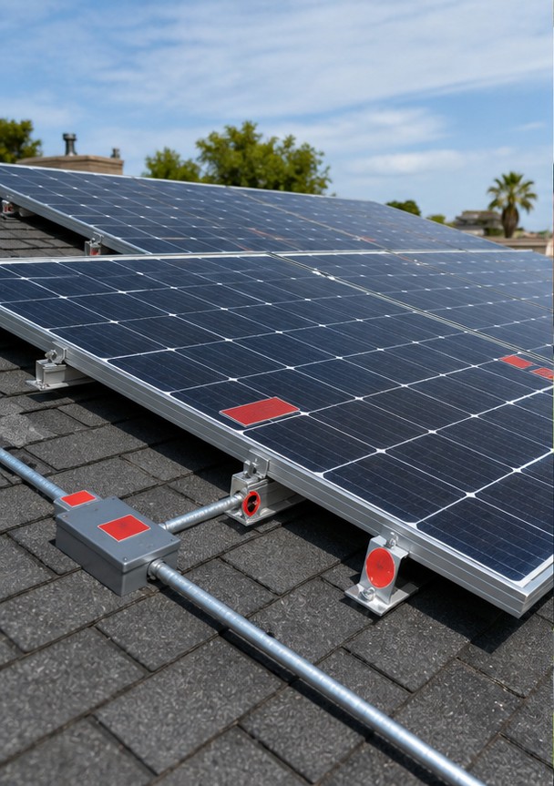
A solar combiner box collects the outputs of multiple photovoltaic strings or inverters and delivers them through one or more larger feeders. In a DC array, it centralizes string fuses, surge protection, isolation and optional monitoring. On the AC side, a combiner aggregates inverter outputs with AC-rated breakers and busbars. This guide explains PV combiner box functions, sizing, components, enclosure requirements and project specification.
What Is a Combiner Box in a Solar System?
Utility-scale and commercial arrays contain many parallel strings. Running every string directly to a central inverter can create excessive cabling. A DC combiner box terminates several string pairs, provides protection and combines them onto a common positive and negative output. The output then feeds an inverter or a DC collection stage.
A combiner does not increase energy production and should not be added without purpose. Small residential systems with a few strings and an inverter containing integrated protection may not need a separate box. The array architecture and applicable code determine the requirement.
DC Combiner Box vs AC Combiner Box
DC PV combiner
A DC combiner handles photovoltaic direct current before the inverter. Components must be rated for maximum PV voltage, continuous current, reverse current, polarity and DC arc interruption. DC switching is more demanding than equivalent AC switching because current has no natural zero crossing.
AC combiner
An AC combiner joins outputs from string inverters or other AC sources. It uses AC circuit breakers or fuse switches, busbars, metering and surge protection matched to voltage, frequency and fault level. A device carrying an AC rating must not be assumed suitable for the DC side.
LBAJI offers the LHLX-PV24/Z/D photovoltaic DC bus box for DC collection and the LHLX-AC photovoltaic AC bus box for AC aggregation.
Quick Comparison and Selection Table
Use this table as a quick review of the main engineering and procurement decisions explained in the article.
| Decision area | Practical meaning | What to verify |
|---|---|---|
| What Is a Combiner Box in a Solar System? | Utility-scale and commercial arrays contain many parallel strings. | Running every string directly to a central inverter can create excessive cabling. |
| DC Combiner Box vs AC Combiner Box | A DC combiner handles photovoltaic direct current before the inverter. | Components must be rated for maximum PV voltage, continuous current, reverse current, polarity and DC arc interruption. |
| Main DC PV Combiner Components | String fuses protect modules and conductors against reverse current from parallel strings. | Their voltage rating, current rating, DC interrupting capacity and photovoltaic fuse class must match the system. |
| Example: 16-String DC Combiner | Assume 16 parallel strings, each with 14 A short-circuit current. | Before applying project-specific correction factors, total short-circuit current is 224 A. |
| Enclosure and Environmental Requirements | Outdoor combiner boxes face solar heat, UV, rain, dust, condensation, salt and large temperature swings. | Specify an appropriate IP or NEMA rating, UV-resistant materials, corrosion class, gasket system and breathable drain or anti-condensation approach where required. |
Main DC PV Combiner Components
String fuses
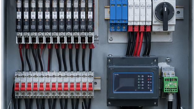
String fuses protect modules and conductors against reverse current from parallel strings. Their voltage rating, current rating, DC interrupting capacity and photovoltaic fuse class must match the system. Fuse sizing considers module maximum series fuse rating, string short-circuit current, correction factors and local rules.
DC surge protection device
SPDs limit transient overvoltage from lightning and switching. Select Type 1, Type 2 or combined protection from the lightning protection design and installation location. Maximum continuous operating voltage must exceed the array’s worst-case open-circuit voltage, including low-temperature correction.
DC disconnect switch
A load-break disconnect provides isolation for maintenance. It must be DC-rated for the system voltage, current, poles and utilization category. Handle interlocking and visible position indication help establish a clear operating state.
Monitoring
String-current sensors, voltage measurement, SPD status, switch position, temperature and communications can identify underperforming strings or failed protection. Monitoring improves diagnostics but does not replace electrical protection.
How to Size a Solar Combiner Box
- Confirm maximum number of parallel strings and module electrical data.
- Calculate maximum system voltage using module open-circuit voltage and minimum site temperature.
- Calculate string and combined current using short-circuit current and required correction factors.
- Check maximum reverse current and module series-fuse rating.
- Select string fuse, holder and disconnect with verified DC ratings.
- Size output busbars and cables for continuous current and temperature rise.
- Check available DC fault current and component interrupting capability.
- Define monitoring channels, communications and auxiliary power.
Example: 16-String DC Combiner
Assume 16 parallel strings, each with 14 A short-circuit current. Before applying project-specific correction factors, total short-circuit current is 224 A. The continuous design current, fuse rating, output switch and cable cannot be selected from 224 A alone; apply the governing PV rules, temperature derating, conductor grouping and component limits. Maximum DC voltage must be calculated at the lowest expected module temperature.
Enclosure and Environmental Requirements
Outdoor combiner boxes face solar heat, UV, rain, dust, condensation, salt and large temperature swings. Specify an appropriate IP or NEMA rating, UV-resistant materials, corrosion class, gasket system and breathable drain or anti-condensation approach where required. A high IP number does not compensate for poorly designed cable glands or a door opened during rain.
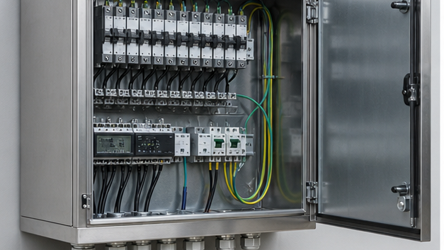
Thermal design matters because fuses, terminals and SPDs generate heat while solar radiation raises enclosure temperature. Components should be spaced for heat dissipation and rated for internal temperature. Stainless steel, coated steel and engineered polymer each have different corrosion, heat and mechanical properties.
Wiring, Polarity and Grounding
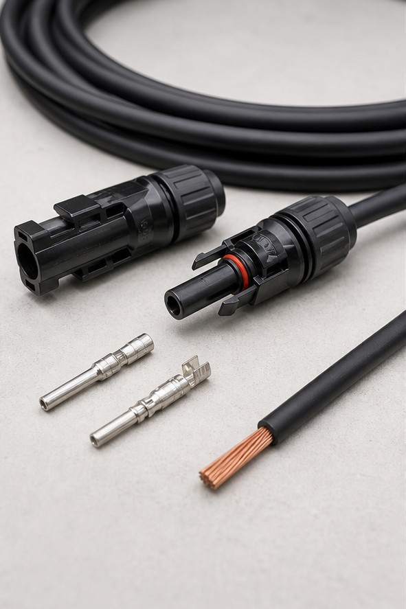
Use PV-rated cable, connectors and glands with the required voltage, temperature and UV rating. Maintain polarity from string to output and separate positive and negative conductors. Torque terminals with calibrated tools and provide strain relief. Protective bonding of metallic enclosures and SPD earth paths should be short and direct. System conductor grounding depends on inverter topology and local requirements.
AC Combiner Design
An AC solar combiner receives several inverter feeders and supplies a transformer or main distribution board. Its busbar current follows inverter output and diversity, while fault level includes grid and other source contributions. Select breakers, busbars, CTs, SPD and enclosure for AC duty and coordinate them with inverter protection and upstream switchgear.
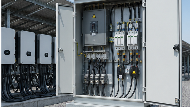
At utility scale, the collected AC output may feed a 35 kV new-energy box-type substation for voltage transformation and grid connection. The combiner, inverter, transformer and MV switchgear ratings should be developed from one system study.
Factory and Site Tests
- Visual and wiring inspection against approved drawings.
- Terminal torque and conductor pull checks.
- Insulation resistance and dielectric tests as applicable.
- Polarity and continuity verification.
- Fuse, SPD, switch and monitoring functional checks.
- Communication mapping and alarm simulation.
- Enclosure and gasket inspection.
- Thermal inspection after operation at representative load.
Common Selection Mistakes
- Using AC breakers or switches on a DC circuit without a verified DC rating.
- Ignoring cold-temperature increase in module open-circuit voltage.
- Selecting fuses only from normal operating current.
- Using an enclosure rating that does not reflect glands and installation.
- Creating long, inductive SPD earth leads.
- Mixing connector brands or types without compatibility approval.
- Omitting spare strings, monitoring channels or future capacity from the design.
Multi-output and monitored combiner boxes
Large arrays may use several combined outputs or string-current monitoring to locate underperforming and faulted strings. Monitoring channels, communications and auxiliary supply must tolerate the same outdoor and surge environment as the power circuit. Input count alone does not define usable capacity.
Information required to select a PV combiner
Provide module Voc, Isc and temperature coefficients, strings in parallel, minimum site temperature, maximum system voltage, inverter inputs, conductor sizes, earthing arrangement and enclosure environment. These inputs determine DC fuse, isolator, SPD, busbar, gland and output-terminal ratings.
Technical references and further reading
The following independent sources support the standards, terminology, calculations, and safety context discussed in this guide:
- U.S. Department of Energy solar photovoltaic resources — Government overview of photovoltaic technology and how PV systems convert solar energy into electrical power.
- IEC 62548-1 photovoltaic array design requirements — Design requirements for PV array wiring, switching, earthing, electrical protection, isolation, and safety.
- OSHA electrical safety requirements — Safety context for electrical construction and distribution equipment associated with power systems.