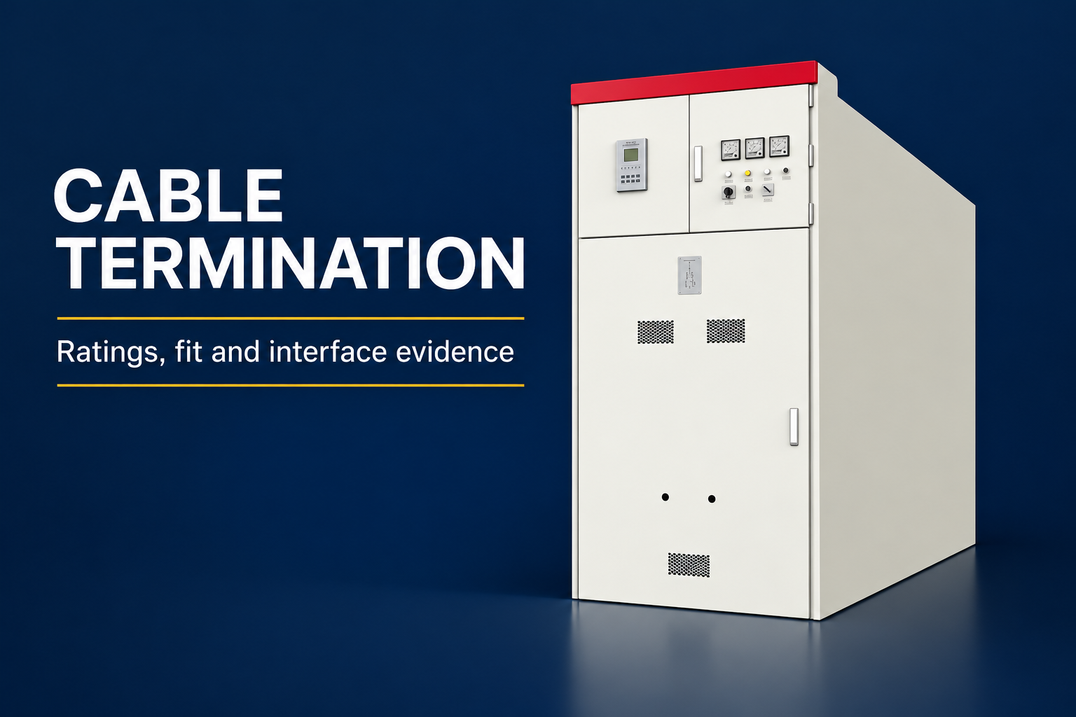
Switchgear cable entry is the physical interface where project cables enter an assembly and reach their approved terminations. A workable specification coordinates entry direction, cable construction, termination accessories, support, bending space, enclosure boundaries and installation responsibility before manufacture. Selecting top or bottom entry alone does not resolve those interfaces. This guide helps buyers prepare the information and drawings needed for review; it does not prescribe field termination methods or claim that a pictured cabinet accepts a particular cable arrangement.
Define the entry interface before ordering
Start with the circuit schedule and the ordered assembly configuration. Identify each incoming and outgoing power circuit, auxiliary supply, control circuit and communication cable. Keep their requirements separate. A power cable termination may need a different compartment, support arrangement and installation sequence from a small control cable, even when both approach from the same building trench.
The LBAJI KYN61-40.5 cabinet illustrated here provides an exterior reference for a metal-enclosed switchgear assembly. Its closed appearance cannot establish internal termination dimensions, permitted conductor sizes or the location of an approved cable entry. Those details belong in the configuration-specific general arrangement and interface drawings supplied for the order.
Top entry and bottom entry are coordination choices
Bottom entry can align an assembly with a cable trench or raised floor, but the route must allow the actual cables to turn, rise and reach their connection points without transferring unsupported mechanical loads into terminals. Coordinate trench edges, cover removal, fire barriers and access before fixing the cabinet position. A trench that fits the lineup footprint may still be unsuitable for its cable arrangement.
Top entry changes the building interface. Review overhead tray levels, entry plates, support positions, installation access and the environmental boundary above the equipment. Do not assume that rotating a gland plate or cutting a new opening makes a bottom-entry design suitable for top entry. Obtain written approval for the intended configuration and its verification consequences.

Build a cable schedule that supports engineering review
For each circuit, provide conductor material and size, number of conductors or cores, insulation system, screen or armor construction, overall diameter and quantity of parallel cables. Include the cable manufacturer’s bending requirements and the proposed termination accessory. Describe cable characteristics from the actual selected cable data sheet, rather than a generic size designation copied from an earlier project.
Identify which information is fixed and which remains provisional. If the cable supplier has not been selected, issue a stated design envelope and a deadline for confirmation. The switchgear manufacturer should identify what can be reserved at that stage and what cannot be released for manufacture without final cable and accessory information.
Termination space is more than a connection height
A termination interface includes the connection point, accessory body, stress-control arrangement where applicable, cable approach and the space needed for assembly and inspection. Dimensions should be checked as a complete arrangement. A connection point can be at an acceptable height while a large accessory or parallel cable group makes the proposed installation impractical.
Ask for a coordinated drawing showing the cable entry zone, terminal positions and allowable installation envelope. The cable accessory supplier and equipment manufacturer should confirm compatibility within their respective scopes. Do not publish an assumed universal clearance or bending radius: those requirements vary with equipment design, voltage system, cable construction and the selected accessory.
Reference context: IEC 62271-200 metal-enclosed AC switchgear scope. This original qualitative checklist organizes project decisions; it is not a reproduced standard or a substitute for approved criteria.
| Review item | Information to exchange | Evidence to retain |
|---|---|---|
| Entry direction | Top or bottom route and entry zone | Approved assembly and building interface drawing |
| Cable construction | Conductor, insulation, diameter, screen and armor | Selected cable data sheet and circuit schedule |
| Termination arrangement | Accessory type, connection and installation envelope | Equipment and accessory compatibility confirmation |
| Mechanical support | Cable weight, support locations and load boundaries | Coordinated support design with assigned responsibility |
| Enclosure boundary | Entry plate, sealing and modified openings | Approved arrangement and verification record |
| Completion | Installed arrangement and inspection access | As-built drawings and signed interface release |
Coordinate mechanical loads and cable support
Cable weight, installation forces and service movement need an intentional support path. The termination should not become an unintended cable hanger. Establish who designs and supplies supports inside and outside the assembly, where the support boundary lies and which loads the manufacturer permits at the equipment interface. Route changes after delivery require a renewed review of those assumptions.
Support details also influence maintainability. Check whether an individual cable or termination can be inspected or replaced without disturbing adjacent circuits beyond the approved work scope. A tightly packed arrangement may meet a drawing dimension but create difficult access for future qualified maintenance. Record access constraints while design choices are still available.

Preserve the enclosure and compartment boundaries
An entry opening affects more than cable fit. Plates, glands, seals and surrounding interfaces may contribute to the assembly’s protection against environmental exposure. Verify the completed installation, including site-supplied parts. The cabinet’s published enclosure classification should not be assumed to survive an unapproved opening, missing seal or substituted entry system.
Compartment boundaries and pressure-relief arrangements also need review where relevant to the specified equipment. Avoid routing cables through reserved spaces or obstructing a designed relief path. The manufacturer should identify installation restrictions in the supplied documentation. Exterior product images cannot prove an internal-arc classification or establish that a modified cable compartment remains within its assessed configuration.
Address single-core cable interfaces explicitly
Where single-core power cables are proposed, identify their arrangement and the materials through which they pass. Electromagnetic and thermal effects at metallic interfaces require a project-specific engineering review. Do not choose entry-plate materials or group cable penetrations merely by copying a photograph of another installation. Confirm the approved arrangement with the equipment and cable-system designers.
Keep screen, armor and protective bonding responsibilities visible in the same interface package. These connections serve different functions and should follow the approved system design. This article does not specify a bonding scheme or permit work on energized equipment. Qualified personnel must follow applicable isolation, verification and electrical work requirements for installation and inspection.
Separate power, control and communication routes
A crowded entry area can blur the separation between high-energy power circuits and sensitive control or communication circuits. Identify approved routes, termination zones and crossing arrangements on the equipment drawings. The design should account for the actual circuit types, shielding requirements and manufacturer’s instructions rather than relying on an arbitrary visual gap.
Check whether the control entry remains accessible after the power cables are installed. A common coordination failure is to finish the large power connections first and discover that auxiliary terminals or gland plates are obstructed. Request a practical installation sequence and document any removable parts, access restrictions or inspections required before subsequent work closes the space.

Agree the supply and installation boundaries
Use a responsibility schedule for entry plates, glands, termination kits, lugs, supports, sealing systems and bonding materials. Identify who selects, supplies, installs and accepts each item. An accessory may be commercially excluded from the switchgear supply yet remain essential to the completed interface; an exclusion does not eliminate the engineering coordination needed before manufacture.
Record the evidence required from each party. A manufacturer drawing, accessory compatibility statement, installation instruction and contractor completion record answer different questions. Keep them connected by circuit and equipment reference. This makes quotation comparison more reliable and prevents an inexpensive offer from appearing complete simply because its interface obligations are unclear.
Review changes before drilling or cutting
When the installed cable differs from the approved schedule, stop the affected interface release and obtain a coordinated revision. Differences in diameter, accessory length, parallel quantity or approach direction can affect the enclosure opening, terminal loading and installation envelope. Document the change even if the substitute cable has an apparently equivalent electrical rating.
Site modifications should follow the manufacturer’s written approval and the project’s change-control process. Record the changed drawing, parts, inspection requirements and effect on verification. An installer should not have to infer from a delivery photograph which plates may be removed or where a new penetration is permitted. Resolve that uncertainty before work proceeds.
Receiving and handover checks
At receiving, compare the supplied cable interface documentation with the ordered configuration and inspect accessible shipping condition without opening energized equipment or exceeding the receiving scope. Confirm that separately shipped interface parts can be traced to their intended locations. Record missing drawings or damaged components as hold points rather than improvising substitutes during installation.
At handover, retain the final circuit schedule, approved entry arrangement, accessory details, support records and as-built changes. The acceptance package should show that the completed interface matches the approved design. Routine factory testing and successful energization do not independently establish that every site-installed cable support, seal and termination interface has been correctly completed.
A practical design-review example
Consider an industrial feeder originally specified with one cable per phase and bottom entry. During procurement, the cable design changes to parallel conductors. The switchgear current rating alone cannot decide whether the change is acceptable. The team must reassess terminal connections, cable grouping, support loads, bending space, gland plate arrangement and the installation sequence against the actual revised cable data.
A useful resolution is a revised coordinated drawing with written equipment and accessory confirmations, assigned supply boundaries and an updated inspection plan. The example deliberately gives no universal dimensions or conductor capacities. Its purpose is to show why an apparently small cable change should trigger an interface review before the assembly reaches site.
Frequently asked questions
Can any switchgear cabinet be converted from bottom entry to top entry?
No. The manufacturer must confirm the ordered configuration, permitted openings, internal arrangement and verification consequences. Appearance alone cannot establish conversion suitability.
Is cable size enough information for the switchgear supplier?
No. Cable construction, overall diameter, parallel quantity, termination accessories, approach direction and mechanical support information are also needed for a coordinated review.
Can an enclosure IP rating be assumed after cable installation?
Only the approved completed arrangement can support that conclusion. Site openings, entry parts and seals need review; an enclosure label does not approve arbitrary modifications.
Who should provide the cable termination kit?
The project responsibility schedule should identify selection, supply, installation and acceptance. Equipment and accessory compatibility still need confirmation regardless of who purchases the kit.
Do the article images show an approved cable termination layout?
No. They are exterior illustrations based on a real LBAJI product. Obtain configuration-specific drawings and instructions before selecting or installing the actual cable interface.
Technical sources and related equipment
Standard catalogue pages establish document scope; compliance and acceptance require the applicable full documents and project engineering review.
- IEC 62271-200 metal-enclosed AC switchgear scope
- IEC 60529 enclosure protection classification
- 29 CFR 1910.333 electrical work practices, official 2025 edition
- LBAJI KYN61-40.5 Armouring Removable AC Metal Enclosed Switchgear
- switchgear equipment fundamentals
- switchgear verification and testing
- factory acceptance witness records
Further learning: equipment functions
This independent educational introduction explains the equipment background. It does not demonstrate a safe work procedure for the specific assembly. Source: Gaurav J – TheElectricalGuy.
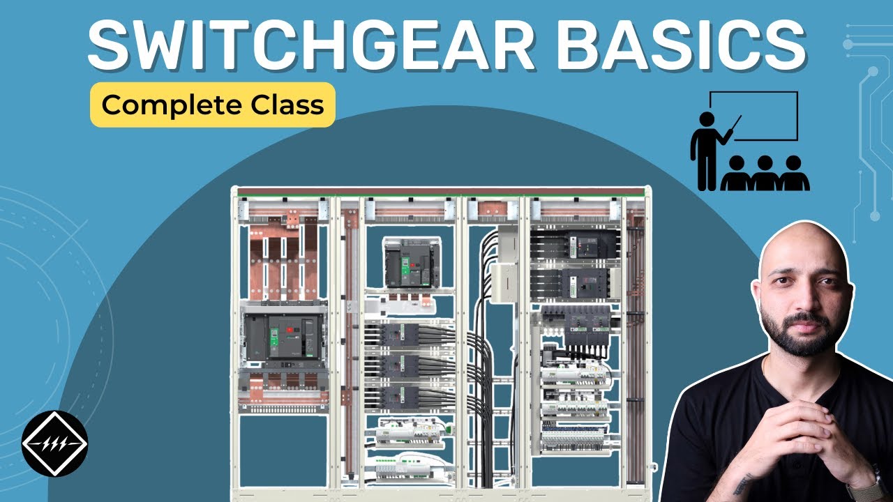
Watch Switchgear Basics: Complete Beginner's Guide | TheElectricalGuy