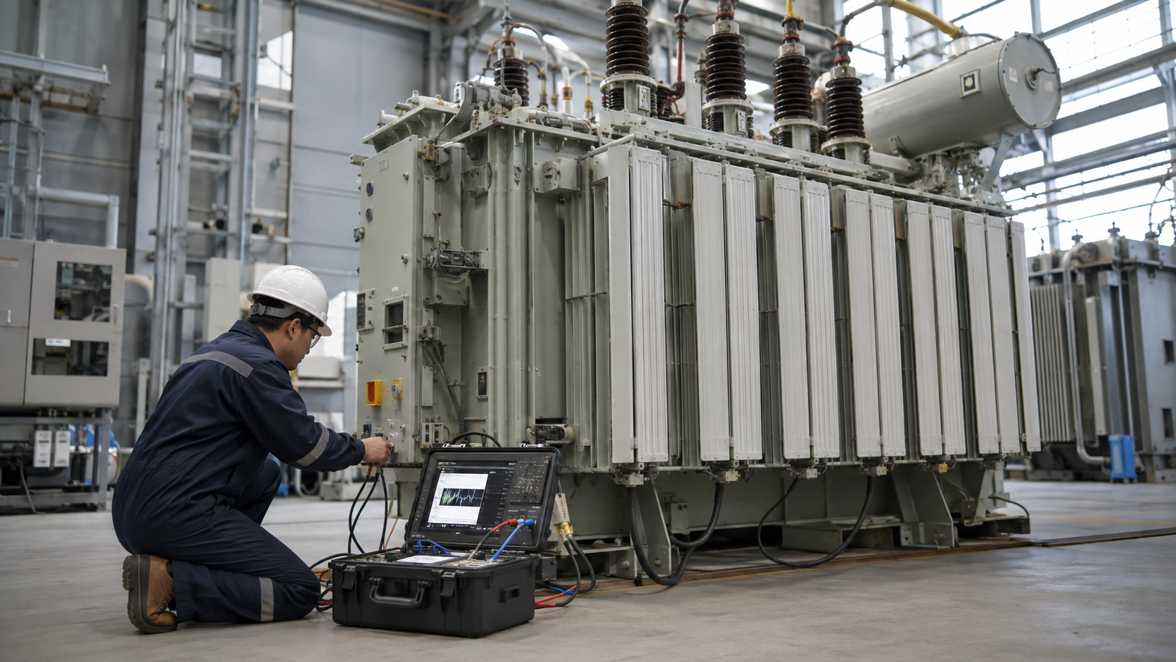
A current transformer (CT) converts a large primary current into a smaller, standardized secondary current that meters and protection relays can safely measure. Its apparent simplicity hides important design choices: construction, ratio, accuracy class, burden, saturation performance and installation polarity all affect the result. This guide explains current transformer types and construction, then shows how to specify CTs for metering and protection inside transformers and switchgear.
What Does a Current Transformer Mean?
A current transformer is an instrument transformer connected in series with the power circuit. The primary may be a cable, busbar or a dedicated winding. Alternating primary current produces magnetic flux in the core, inducing a proportional secondary current. Common secondary ratings are 5 A or 1 A, depending on the system and standard.
A CT provides measurement scaling and electrical isolation, but it does not reproduce every current perfectly. Ratio error, phase displacement, core losses and saturation must remain within limits for the intended duty.
How a Current Transformer Works
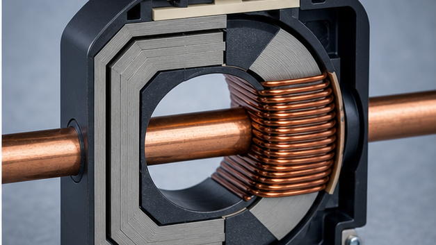
In an ideal CT, primary ampere-turns equal secondary ampere-turns. If a bar-primary CT has one primary turn and 200 secondary turns, 1,000 A primary current would ideally produce 5 A secondary current. Real CTs require magnetizing current, so selection is based on standardized accuracy classes and rated burden.
Never open-circuit the secondary of an energized CT. With no secondary current opposing primary flux, the core voltage can rise to a dangerous level and damage insulation or expose personnel. Shorting links and test blocks should be provided so meters or relays can be removed safely by qualified personnel.
Quick Comparison and Selection Table
Use this table as a quick review of the main engineering and procurement decisions explained in the article.
| Decision area | Practical meaning | What to verify |
|---|---|---|
| What Does a Current Transformer Mean? | A current transformer is an instrument transformer connected in series with the power circuit. | The primary may be a cable, busbar or a dedicated winding. |
| How a Current Transformer Works | In an ideal CT, primary ampere-turns equal secondary ampere-turns. | If a bar-primary CT has one primary turn and 200 secondary turns, 1,000 A primary current would ideally produce 5 A secondary current. |
| Current Transformer Construction | The main components are a magnetic core, insulated secondary winding, primary current path, terminals, insulation system and enclosure. | Core material and cross-section influence magnetizing current and saturation. |
| Main Current Transformer Types | A window CT has an opening through which a cable or busbar passes. | That conductor forms a one-turn primary. |
| Metering CT vs Protection CT | A metering current transformer is optimized for accuracy around normal load and is often designed to saturate before excessive fault current reaches connected instruments. | A protection CT must reproduce high fault current accurately enough for the relay to operate correctly. |
Current Transformer Construction
The main components are a magnetic core, insulated secondary winding, primary current path, terminals, insulation system and enclosure. Core material and cross-section influence magnetizing current and saturation. The secondary winding uses many turns of copper conductor distributed to control leakage flux. Medium-voltage CTs also require an insulation system rated for the network voltage and impulse level.
Some switchgear CTs contain multiple cores. One core can feed revenue or operational metering while separate protection cores feed overcurrent, earth-fault or differential relays. Each core has its own ratio, class and burden and must be wired only to its assigned circuit.
Main Current Transformer Types
Window or ring current transformer
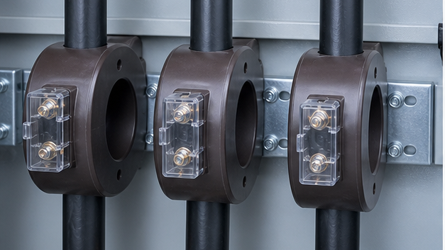
A window CT has an opening through which a cable or busbar passes. That conductor forms a one-turn primary. The construction is compact, easy to install and widely used in panels. A split-core version can be fitted around an existing conductor for monitoring, but jointed cores may have different accuracy and should not be assumed suitable for protection without verification.
Bar-primary current transformer
A bar CT includes a fixed primary conductor through its core. Terminals connect the bar directly into the power circuit. It provides controlled mechanical and electrical construction for switchgear but must be rated for continuous current and short-circuit forces.
Wound-primary current transformer
A wound CT has several primary turns and is useful for lower primary-current ratios where a single primary turn would not achieve suitable performance. Both primary and secondary require insulation and terminals, making the construction more complex.
Bushing and cable current transformers
Bushing CTs fit around transformer or circuit-breaker bushings. Cable CTs fit around power cables and may be used for phase or earth-fault measurement. A core-balance CT surrounds all phase conductors so normal vector current sums to nearly zero; residual current appears during an earth fault.
Metering CT vs Protection CT
A metering current transformer is optimized for accuracy around normal load and is often designed to saturate before excessive fault current reaches connected instruments. A protection CT must reproduce high fault current accurately enough for the relay to operate correctly. Its knee-point voltage, excitation curve or composite-error class may therefore be more important than fine accuracy at normal load.
Do not place a protection relay and precision meter on one core unless the design explicitly demonstrates that burden and saturation meet both requirements. Separate cores make performance and testing clearer.
Understanding CT Ratio
A ratio such as 600/5 A means 600 A primary current corresponds nominally to 5 A secondary current. The ratio is 120:1. If the secondary measures 3 A, the indicated primary current is approximately 360 A before applying instrument corrections.
The selected primary rating should cover maximum expected continuous load without making normal current too small for useful accuracy. Multi-ratio CTs provide taps, but the unused terminals and actual connected ratio must be documented.
Accuracy Class, Burden and Saturation
Rated burden is the impedance or VA load connected to the secondary at rated current. It includes the meter or relay, test switch, terminals and lead resistance. Excessive burden increases error and can cause earlier saturation. A 1 A secondary often reduces lead burden on long cable runs because power loss varies with current squared.
Metering accuracy classes state permitted ratio and phase errors over a current range. Protection classes state performance at rated accuracy-limit current or define knee-point and secondary-resistance requirements. Standards use different class designations, so the purchase specification must cite the applicable edition and full class—not only a number.
How to Size a Current Transformer
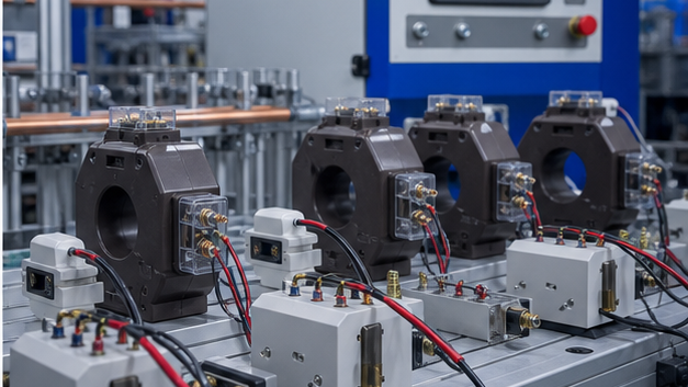
- Confirm maximum system voltage and required insulation level.
- Calculate normal, emergency and future maximum current.
- Select a standard primary ratio that provides useful resolution without overload.
- Choose 1 A or 5 A secondary to match the relay, meter and wiring distance.
- Calculate total burden from devices and lead resistance.
- Select metering or protection class from the application and governing standard.
- Check short-time thermal and dynamic current withstand against the fault study.
- Confirm window size, conductor arrangement, terminals, polarity and mounting.
CTs in Switchgear and Transformer Protection
In KYN28A-12 medium-voltage switchgear, CTs supply feeder metering and protection functions around the cable or bus path. Higher-voltage assemblies such as KYN61-40.5 switchgear require CT insulation and dimensions appropriate to the voltage class.
Power-transformer differential protection compares currents on each side after accounting for ratio and vector-group phase shift. CT ratio, polarity, saturation and relay compensation must all be coordinated. For a project using a 35 kV oil-immersed power transformer, the transformer data and fault study should be supplied with the switchgear CT schedule. For a separate distribution-transformer example and its single-phase ratings, see the single-phase transformer fundamentals guide. For residual-current sensing and relay matching, see the core balance CT selection guide.
Installation and Testing Checklist
- Verify nameplate ratio, class, burden and terminal markings.
- Confirm P1/P2 and S1/S2 polarity against protection drawings.
- Earth the secondary circuit at the designated single point.
- Check that all primary conductors pass through a core-balance CT in the correct direction.
- Perform ratio, polarity, insulation and excitation tests as specified.
- Prove secondary injection and the complete relay-to-breaker trip chain.
- Keep secondary circuits shorted before disconnecting connected equipment.
Can a Current Transformer Measure DC?
A conventional magnetic CT requires alternating flux and cannot measure steady DC. DC current measurement uses Hall-effect sensors, fluxgate transducers or shunts. A device marketed as a “DC current transformer” normally uses active electronics and should be specified by its bandwidth, accuracy, isolation and auxiliary-power needs.
CT burden, accuracy and knee point
CT burden is the combined impedance of meters, relays, leads and terminals. Excess burden increases error and can push the core into saturation. Metering CTs emphasize accuracy near normal current; protection CTs must reproduce high fault current long enough for the relay to operate. Knee-point or excitation data is especially important in high-impedance and differential schemes.
CT polarity and secondary safety
Polarity marks establish the direction used by power, differential and directional functions. Verify terminal identification and one-point secondary grounding against the approved drawing. Never open an energized CT secondary: the core flux and secondary voltage can rise to dangerous levels. Use shorting terminals before removing a relay or meter.
Technical references and further reading
The following independent sources support the standards, terminology, calculations, and safety context discussed in this guide:
- IEC 60076-1 power transformer standard — Scope, terminology, ratings, connection symbols, testing, safety, and general requirements for power transformers.
- U.S. Department of Energy: Distribution Transformers — Official definitions, efficiency requirements, test procedures, and regulatory resources for distribution transformers.
- OSHA electric power transmission and distribution requirements — Safety requirements relevant to construction and work around electric power transmission and distribution equipment.