Transformer impedance decides how much fault current your switchgear must clear and how far voltage dips when large loads start.
Buyers often treat percent impedance as a nameplate detail, then discover protection and paralleling problems after delivery. This guide explains what Z% controls, the trade-offs behind high and low values, and what to state in an RFQ.
Bring your fault study assumptions and network data before fixing the value with any factory.
Part 1. Why impedance belongs in procurement, not just design
Percent impedance links the transformer to every breaker, cable, and relay downstream. A value chosen casually can force switchgear upgrades that cost more than the transformer itself.
Fixing Z% early keeps the fault study, protection settings, and transformer order aligned.
For related context, see the distribution transformer kVA calculation guide.
For related context, see the loading guide for oil immersed power transformers.
Part 2. What percent impedance means
Percent impedance is the supply voltage share needed to circulate rated current through a short-circuited secondary winding.

| Aspect | Lower impedance | Higher impedance |
|---|---|---|
| Fault current at secondary | Higher | Lower |
| Voltage drop under load | Smaller | Larger |
| Motor starting support | Stronger | Weaker |
| Switchgear breaking duty | Heavier | Lighter |
| Parallel operation | Must match partner unit | Must match partner unit |
Typical distribution ratings carry catalog values in the 4-6% band, rising for larger units; treat catalog figures as reference, final per issued drawings and the tolerance rules of IEC 60076-1.
Part 3. Impedance and fault current
Secondary fault current is roughly rated current divided by per-unit impedance: a 1000 kVA unit at 5% feeds about twenty times rated current into a close-in fault.
Switchgear breaking capacity, busbar bracing, and cable withstand must all cover that level with margin.
Utilities may also cap fault contribution at the connection point—confirm limits before pushing Z% lower.
Part 4. Impedance, regulation, and motor starting
Higher impedance softens fault duty but deepens voltage drop under load and during motor starting.
Sites with large direct-on-line motors usually push toward lower impedance or a dedicated starting study.
Balance the two effects inside the fault study rather than copying a value from an old project.
Part 5. Short-circuit withstand and through-fault duty
Impedance also sets the mechanical forces windings survive during through-faults; IEC 60076-5 defines the withstand requirements and verification methods.
Ask the factory how the design was verified: a short-circuit type test, calculation per the standard, or both.
Frequent downstream faults age windings, and the through-fault guidance in IEEE C57.109 helps protection engineers set sensible exposure limits.
Part 6. Product recommendation and Fit Boundary
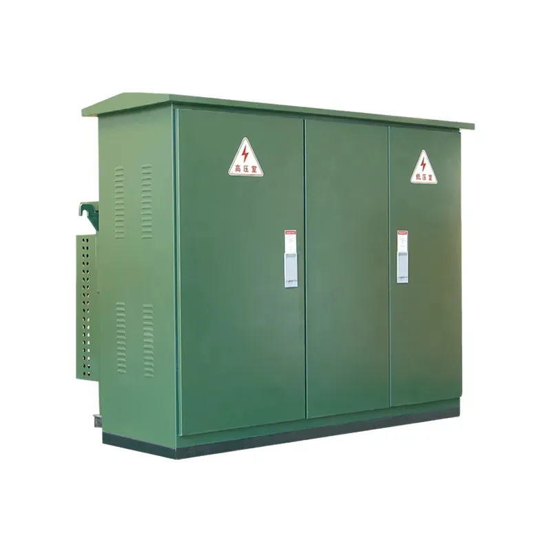
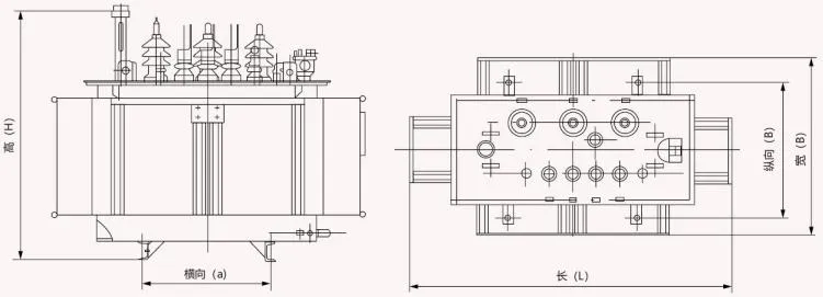
Product recommendation: Confirm the impedance band during series selection, before model drawings are issued. Start at the transformer product category, then review the S□-M oil-immersed power transformer series and the SC(B) resin insulated dry transformer series against the approved specification.
| Better fit | Poor fit without extra study |
|---|---|
| Projects with a current fault study and protection plan | Copying impedance from an unrelated legacy unit |
| Buyers coordinating utility fault limits early | Fixing Z% after switchgear is already ordered |
| Teams comparing bids on one impedance tolerance basis | Ignoring tolerance bands when comparing bids |
Submit the rated kVA and voltage combination, vector group and tap range, no-load and load losses, cooling method and enclosure, and short-circuit impedance target through Contact Us for model-specific confirmation.
Part 7. Common impedance mistakes
- Choosing the lowest quoted impedance for stiffness without checking breaker duty.
- Comparing bids with different impedance tolerances or reference temperatures.
- Forgetting that paralleled units need matched impedance to share load.
- Overlooking utility fault-level caps at the point of connection.
- Treating catalog Z% as exact when production tolerance applies per standard.
- Skipping short-circuit withstand evidence for motor-heavy or fault-prone feeders.
FAQ
What is transformer percent impedance?
Percent impedance is the voltage share needed to drive rated current through a short-circuited secondary; it governs fault current and voltage drop behavior.
How does impedance affect fault current?
Fault current scales inversely with impedance: at 5%, a close-in secondary fault draws roughly twenty times rated current until protection clears it.
Is lower impedance always better?
No—lower Z% improves regulation and motor starting but raises breaking duty on every downstream device; the fault study decides the balance.
What impedance tolerance applies to catalog values?
IEC 60076-1 allows a production tolerance on declared impedance; ask the factory for the guaranteed band and compare bids on that basis.
How does impedance affect parallel operation?
Units sharing a bus need closely matched impedance; mismatch shifts load onto the lower-impedance unit and can overheat it.
Can I specify a non-standard impedance?
Often yes within design limits—state the target and tolerance in the RFQ and let the factory confirm feasibility and the loss impact.
What short-circuit data should the RFQ include?
System fault level at the connection point, required withstand evidence, protection philosophy, and any utility cap on fault contribution.