Converting kVA to amps is one of the most common calculations in transformer, generator, cable and switchgear selection. The arithmetic is simple, but the result is only correct when the phase arrangement and voltage are entered correctly. This guide gives the single-phase and three-phase formulas, worked examples from 15 kVA to 75 kVA, reverse amps-to-kVA conversions, and the practical checks needed before using a calculated current as an equipment rating.
What Does kVA Mean?
kVA means kilovolt-amperes and measures apparent power. One kVA equals 1,000 volt-amperes. Apparent power includes the portion converted into useful work and the reactive portion exchanged by inductive or capacitive loads. Transformers and generators are normally rated in kVA because their heating is mainly related to voltage and current, not to the load power factor alone.
kW measures real power. For a balanced load, the relationship is kW = kVA × power factor. A 100 kVA load at 0.8 power factor uses 80 kW of real power. Do not treat kVA and kW as equal unless the power factor is 1.0.
Single-Phase kVA to Amps Formula
For a single-phase AC circuit:
Current (A) = kVA × 1,000 ÷ Voltage (V)
Example: a 25 kVA single-phase transformer with a 240 V secondary supplies:
25 × 1,000 ÷ 240 = 104.2 A
At 480 V, the same 25 kVA corresponds to 52.1 A. This demonstrates why a kVA figure cannot be converted to amperes without knowing the voltage.
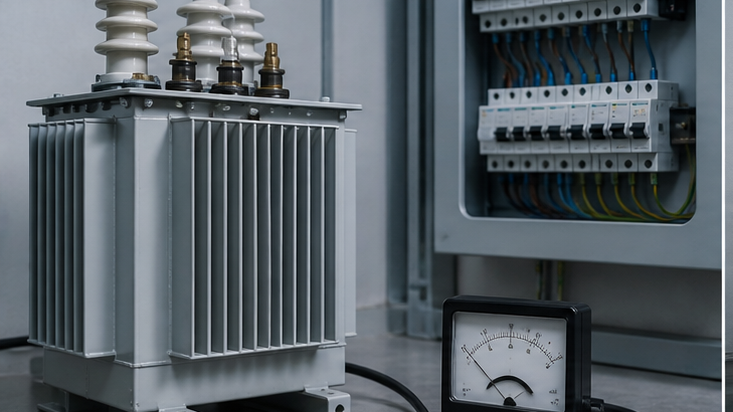
Three-Phase kVA to Amps Formula
For a balanced three-phase circuit using line-to-line voltage:
Current (A) = kVA × 1,000 ÷ (√3 × Voltage)
Because √3 is approximately 1.732, a 75 kVA three-phase transformer at 400 V supplies:
75 × 1,000 ÷ (1.732 × 400) = 108.3 A
At 480 V, the same 75 kVA supplies approximately 90.2 A. The formula assumes a balanced three-phase load. Significant phase imbalance requires a phase-by-phase current review and may limit usable transformer capacity.
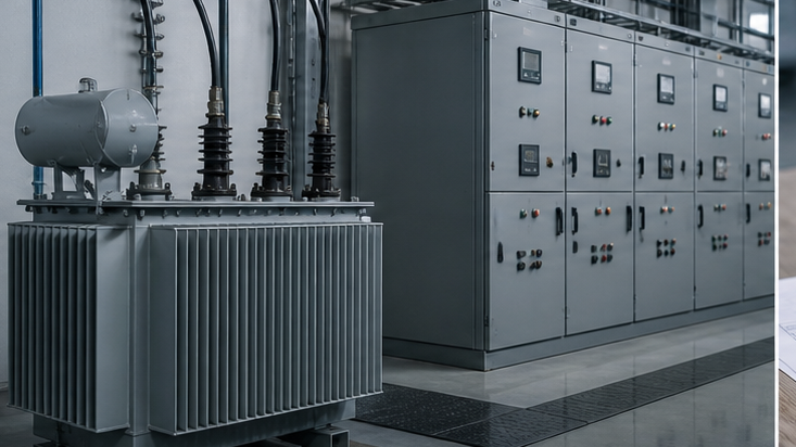
Quick kVA-to-Amps Examples
| Transformer rating | Single-phase 240 V | Three-phase 400 V | Three-phase 480 V |
|---|---|---|---|
| 15 kVA | 62.5 A | 21.7 A | 18.0 A |
| 25 kVA | 104.2 A | 36.1 A | 30.1 A |
| 30 kVA | 125.0 A | 43.3 A | 36.1 A |
| 45 kVA | 187.5 A | 65.0 A | 54.1 A |
| 75 kVA | 312.5 A | 108.3 A | 90.2 A |
These values are calculated full-load currents, not automatic cable or breaker selections. Wiring rules may require continuous-load factors, correction factors and a standard protective-device size. Transformer inrush and short-circuit coordination also affect breaker selection.
How to Convert Amps to kVA
Reverse the formulas when current and voltage are known:
- Single phase: kVA = Volts × Amps ÷ 1,000
- Three phase: kVA = √3 × Volts × Amps ÷ 1,000
Example: a balanced three-phase load draws 200 A at 400 V:
1.732 × 400 × 200 ÷ 1,000 = 138.6 kVA
If the measured power factor is 0.85, approximate real power is 138.6 × 0.85 = 117.8 kW. Measurements should cover representative operating conditions; a short reading may miss peak demand or intermittent loads.
kVA, Watts and Power Factor
For AC systems, converting kVA to watts requires power factor:
Watts = kVA × 1,000 × power factor
To convert watts to kVA:
kVA = Watts ÷ (1,000 × power factor)
A 50 kW load at 0.8 power factor requires 62.5 kVA. At 0.95 power factor it requires 52.6 kVA. Improving power factor can reduce line current and free capacity, but correction capacitors must be assessed for harmonics, resonance and switching transients.
Transformer Primary and Secondary Current
A transformer has approximately the same kVA on both sides, excluding losses, but its current changes inversely with voltage. A three-phase 1,000 kVA transformer with a 10 kV primary and 400 V secondary has approximate full-load currents of:
- Primary: 1,000,000 ÷ (1.732 × 10,000) = 57.7 A
- Secondary: 1,000,000 ÷ (1.732 × 400) = 1,443 A
The low-voltage switchboard and busbars therefore carry far more current than the medium-voltage primary equipment. LBAJI’s 35 kV oil-immersed transformer can be configured for project-specific ratings, while packaged projects may integrate transformer and distribution equipment in a YBM-12 prefabricated substation.
From Calculated Load to Transformer Size
Adding every nameplate kW usually overstates normal demand, while using only average measured load may understate peaks. A defensible load schedule separates continuous, intermittent, standby, motor, nonlinear and future loads. Apply documented demand and diversity factors, convert real power to kVA with realistic power factors, and check starting or cyclic duty.

After selecting a preliminary standard kVA rating, verify:
- normal and emergency loading profile;
- ambient temperature, altitude and cooling method;
- motor-starting voltage drop;
- harmonic heating from converters, UPS systems and LED loads;
- future expansion and parallel operation;
- available short-circuit current on the secondary;
- upstream and downstream protection coordination.
Common Calculation Mistakes
- Using the single-phase formula for three phase. The three-phase equation requires √3 when line-to-line voltage is used.
- Mixing kW with kVA. Include power factor when converting real and apparent power.
- Entering the wrong voltage. Confirm whether the drawing gives line-to-line or line-to-neutral voltage.
- Treating calculated current as breaker size. Apply the governing wiring standard, load duty, inrush and coordination study.
- Ignoring efficiency. Input kW is greater than output kW because equipment has losses.
- Ignoring harmonics and imbalance. RMS current and neutral loading may exceed a simple balanced fundamental-frequency estimate.
Applying Results to Switchgear Selection
Calculated full-load current establishes a minimum continuous-current requirement, but switchgear selection also depends on fault level, insulation rating, enclosure, internal-arc requirement and operating duty. Medium-voltage distribution can use KYN28A-12 withdrawable switchgear, while compact ring networks may use the LBHB-12 gas-insulated RMU. The final equipment schedule should be checked against the single-line diagram and fault study.
Single-phase versus three-phase conversion
Single-phase current equals kVA × 1,000 ÷ volts. Three-phase current equals kVA × 1,000 ÷ (1.732 × line-to-line volts). The square-root-of-three factor is the most common source of error. Power factor is unnecessary when kVA is already known, but it is required when the starting value is kW.
A reliable calculator workflow
Select phase count first, enter kVA and the actual operating voltage, calculate without premature rounding, and label whether the result is primary or secondary current. Repeat the calculation on both sides of a transformer. The result is full-load current; conductor ampacity, continuous-load factors, ambient derating and protective-device rules require separate checks.
Technical references and further reading
The following independent sources support the standards, terminology, calculations, and safety context discussed in this guide:
- NIST SI units for electric current — Authoritative definitions and relationships for amperes, volts, watts, and ohms.
- NIST Guide to SI electrical conversion factors — Official conversion factors for electricity, magnetism, energy, and related quantities.
- OSHA electrical safety requirements — Safety context for applying electrical calculations to transmission and distribution work.