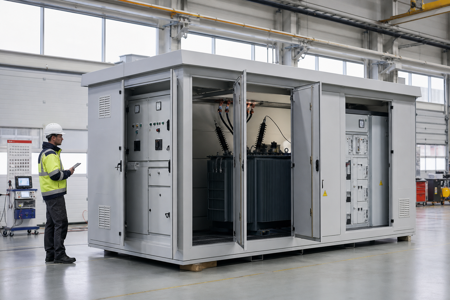
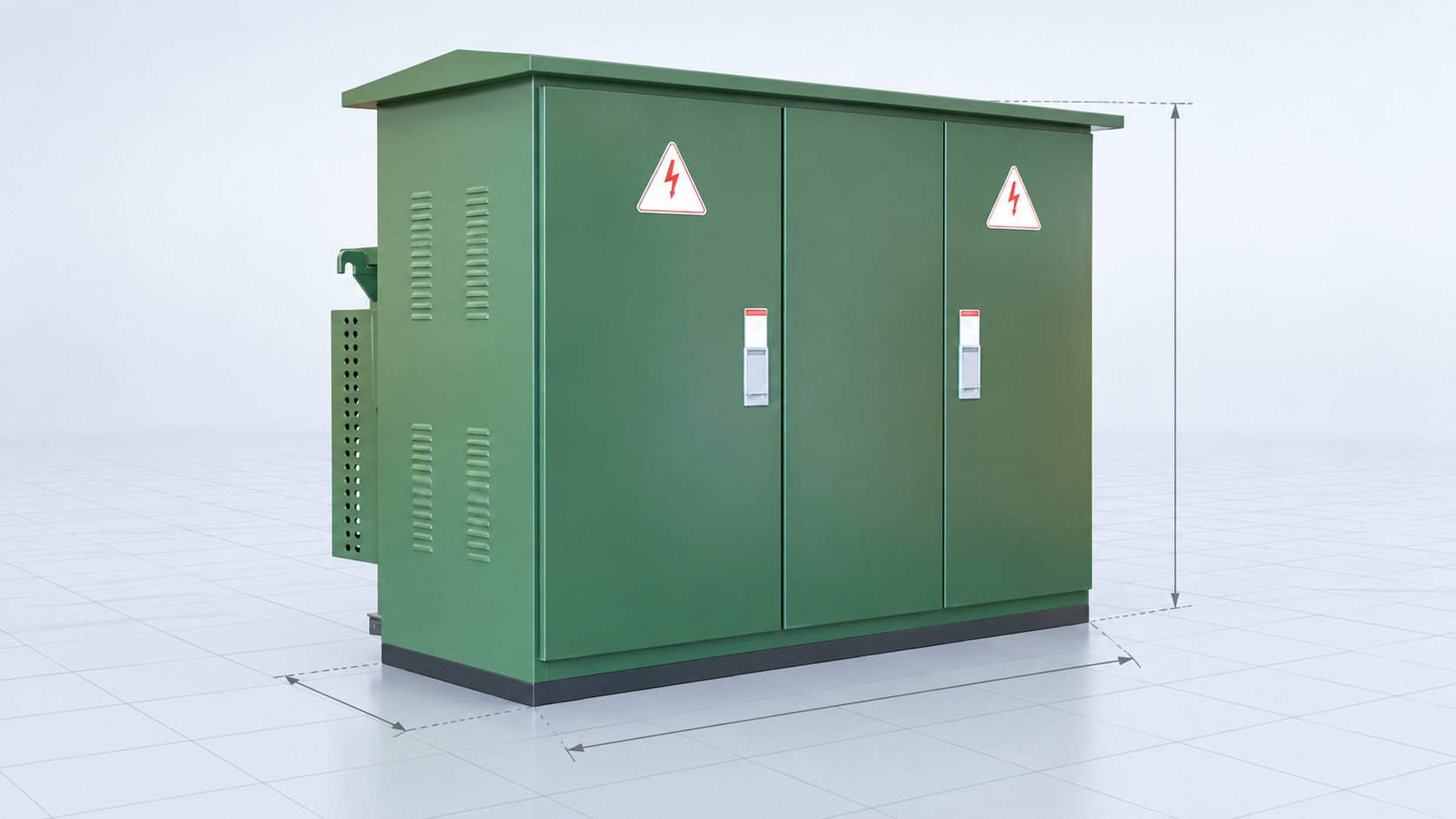
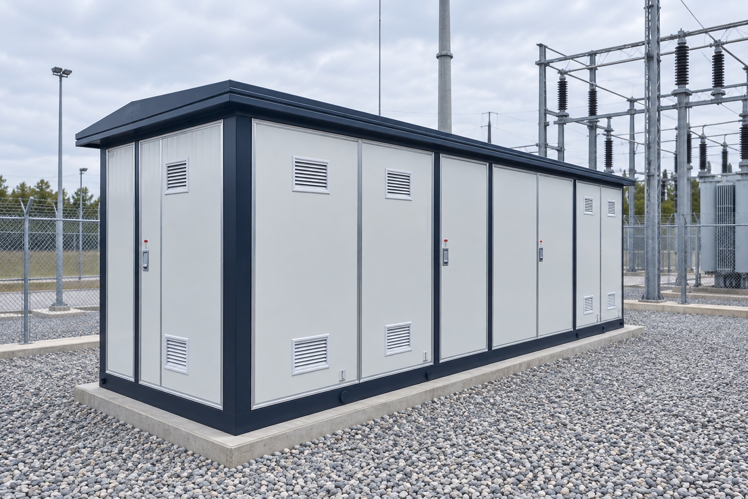
Electrical substation engineering converts system requirements into a coordinated primary, secondary, civil and communications design that can be built, tested, operated and maintained safely. The work spans load flow and fault studies, insulation and grounding, equipment ratings, protection and control, layout, structures, cables, auxiliary systems, cybersecurity, construction sequencing and commissioning. Clear design inputs and interface ownership are as important as calculations.
Key Takeaways
- Freeze the design basis and utility interfaces before detailed engineering.
- Coordinate electrical, civil, structural, protection and communications data.
- Design for construction, testing, operation and maintenance—not drawings alone.
Design Basis and Power-System Studies

The design basis records voltage levels, capacity, reliability criteria, operating configurations, utility fault data, environmental conditions, standards and future expansion. Load-flow studies establish normal and contingency loading and voltage. Short-circuit studies set equipment duty and protection inputs.
Additional studies may include insulation coordination, motor starting, harmonics, transient recovery voltage, arc-flash inputs and reactive compensation. Every result must identify source data, operating case, assumptions and revision.
Primary Equipment and Physical Layout
Engineers select transformers, bus schemes, circuit breakers, disconnectors, instrument transformers, surge arresters, switchgear and reactive equipment. Ratings include voltage insulation, continuous current, fault withstand, switching duty, environmental correction and seismic or wind requirements.
The layout maintains electrical clearances, access, escape paths, lifting and replacement routes, fire separation, oil containment, drainage and future bays. A compact arrangement that cannot be maintained or expanded is not an optimized design.
Protection, Control and Auxiliary Systems
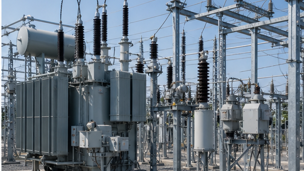
Protection zones and redundancy follow the bus and equipment arrangement. CT and VT data, breaker times, communication channels, DC trip circuits and interlocking are coordinated through schematics and logic diagrams. Settings require fault and coordination studies plus end-to-end validation where communications are involved.
Station service AC, DC batteries and chargers, lighting, HVAC, fire detection, security, SCADA, time synchronization and communications support the primary plant. Loss of an auxiliary system must be included in reliability analysis.
Substation Engineering Stage and Deliverable Matrix
| Stage | Key decisions | Typical deliverables | Gate |
|---|---|---|---|
| Concept | Voltage, capacity, location and bus scheme | Design basis, one-line and site options | Feasibility approval |
| Basic design | Ratings, studies and layout | Study reports, specifications and plans | Technical review |
| Detailed design | Interfaces, wiring and construction data | IFC drawings, schedules and calculations | Constructability review |
| Commissioning | Settings and functional performance | Test plans, results and punch list | Energization approval |
| Handover | As-built and lifecycle data | Records, manuals, spares and training | Owner acceptance |
Construction, Testing and Handover
Issued-for-construction packages should reconcile single-lines, layouts, foundations, grounding, cable schedules, wiring, bills of material and vendor drawings. Interface registers prevent gaps between owner, utility, OEM and contractor scope.
Commissioning progresses from receipt inspection and installation checks through primary, secondary, functional and system tests. As-built drawings, settings, test reports, asset data, spares and training form part of the engineered deliverable, not administrative extras.
Engineering Validation and Safety Boundary
This guide supports specification and procurement; it does not replace a project study, the applicable code, the manufacturer instructions or work by qualified electrical personnel. Verify the following before equipment selection, testing, wiring or energization:
- Use controlled utility source and fault data.
- Apply site altitude, pollution, temperature, seismic and wind conditions.
- Coordinate grounding, lightning, fire and oil-containment designs.
- Independently review protection settings and interlocking logic.
- Verify every drawing against approved vendor data before construction.
Information to Include in the RFQ
A useful quotation must be based on the same technical boundary for every supplier. Include the following information and require all deviations to be listed explicitly:
- Project scope, voltage levels, capacity and reliability criteria.
- Site survey, environmental, geotechnical and utility interface data.
- Required studies, standards, drawings, models and review stages.
- Protection, SCADA, communications and cybersecurity requirements.
- Construction support, commissioning, as-built and training scope.
From Technical Data to an Approved Decision
Use a staged review rather than approving the first catalogue match. Begin with design basis and power-system studies, then reconcile primary equipment and physical layout with protection, control and auxiliary systems. Complete the review with construction, testing and handover. At each stage, record the source document, units, operating case and person responsible for approval. This prevents a value copied from an old drawing, nominal system label or unrelated product from becoming an uncontrolled design input.
Before acceptance, compare the supplier response line by line with the RFQ and mark every exception. Confirm that drawings, calculations, settings, certificates and test reports refer to the exact offered model and revision. Preserve the approved submittal, nameplate data, factory results and commissioning measurements as the maintenance baseline. If a rating, connection, environment or test condition changes, repeat the affected review rather than assuming the original conclusion remains valid.
Document control should identify revision, approval status and superseded files. Field teams should receive the same approved values used for procurement, while commissioning records should capture any authorized change made during installation. This traceability is especially important when equipment is replaced years later: the next engineer needs verified interfaces and test history, not an incomplete description copied from a purchase order.
Coverage Informed by Current Search Results
The current U.S. Google top-20 review repeatedly surfaced themes including quick links, Connect with Us, II. SUBSTATION/SWITCHYARD EQUIPMENT SELECTION AND SIZING (IEC, IS, IEEE) STANDARDS, XX. HV CIRCUIT BREAKERS SIZING, Leave a Comment. The article addresses those user needs in an original engineering and procurement sequence; competitor brand navigation and unrelated sales material were excluded.
Related LBAJI Resources
Continue with substation design and layout guide substation testing and construction LBAJI substations. These resources help connect the calculation or component decision to a complete transformer, switchgear, control or distribution specification.
Technical References and Further Reading
- IEC 61936-1 — Power installations above 1 kV AC.
- IEC 61850 — Substation communication systems.
- OSHA Electric Power Requirements — Safety context for power installations.
Conclusion
Successful substation engineering maintains one controlled design basis from studies through handover. Ratings, layout, protection, civil interfaces and commissioning evidence must agree so the installed station performs in every required operating case.