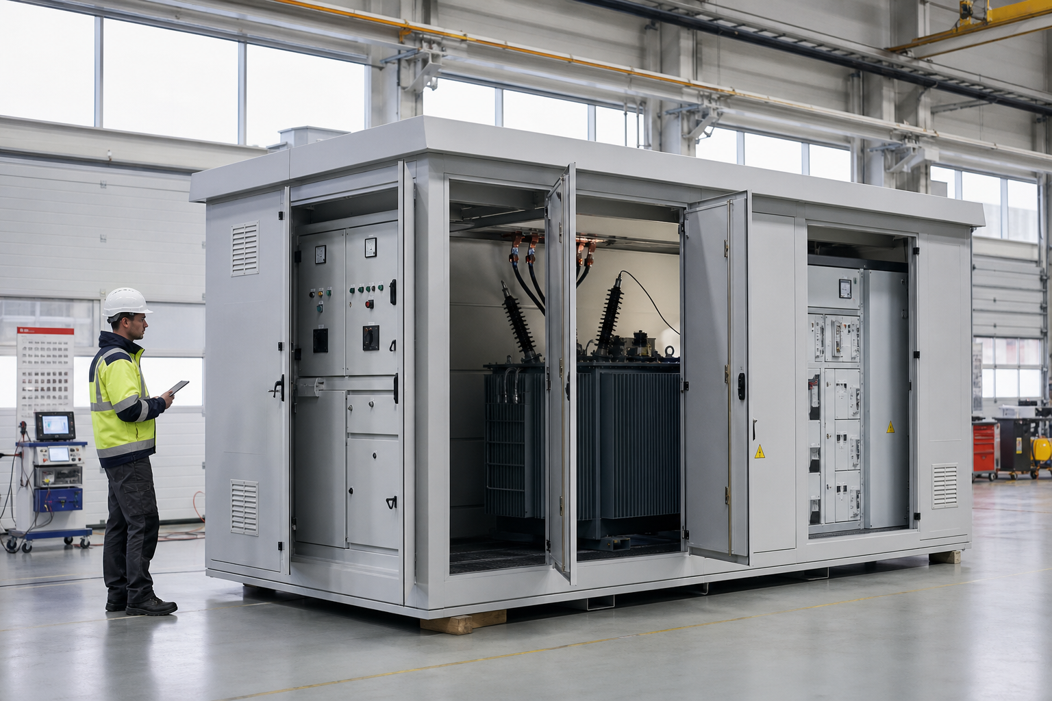
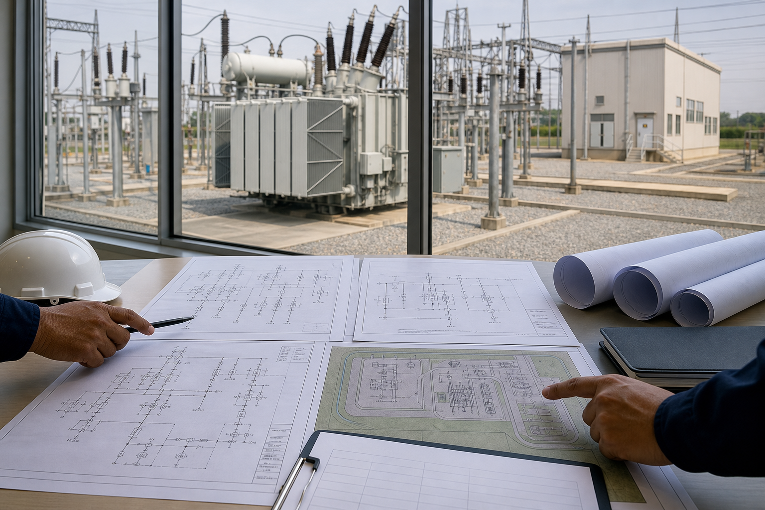
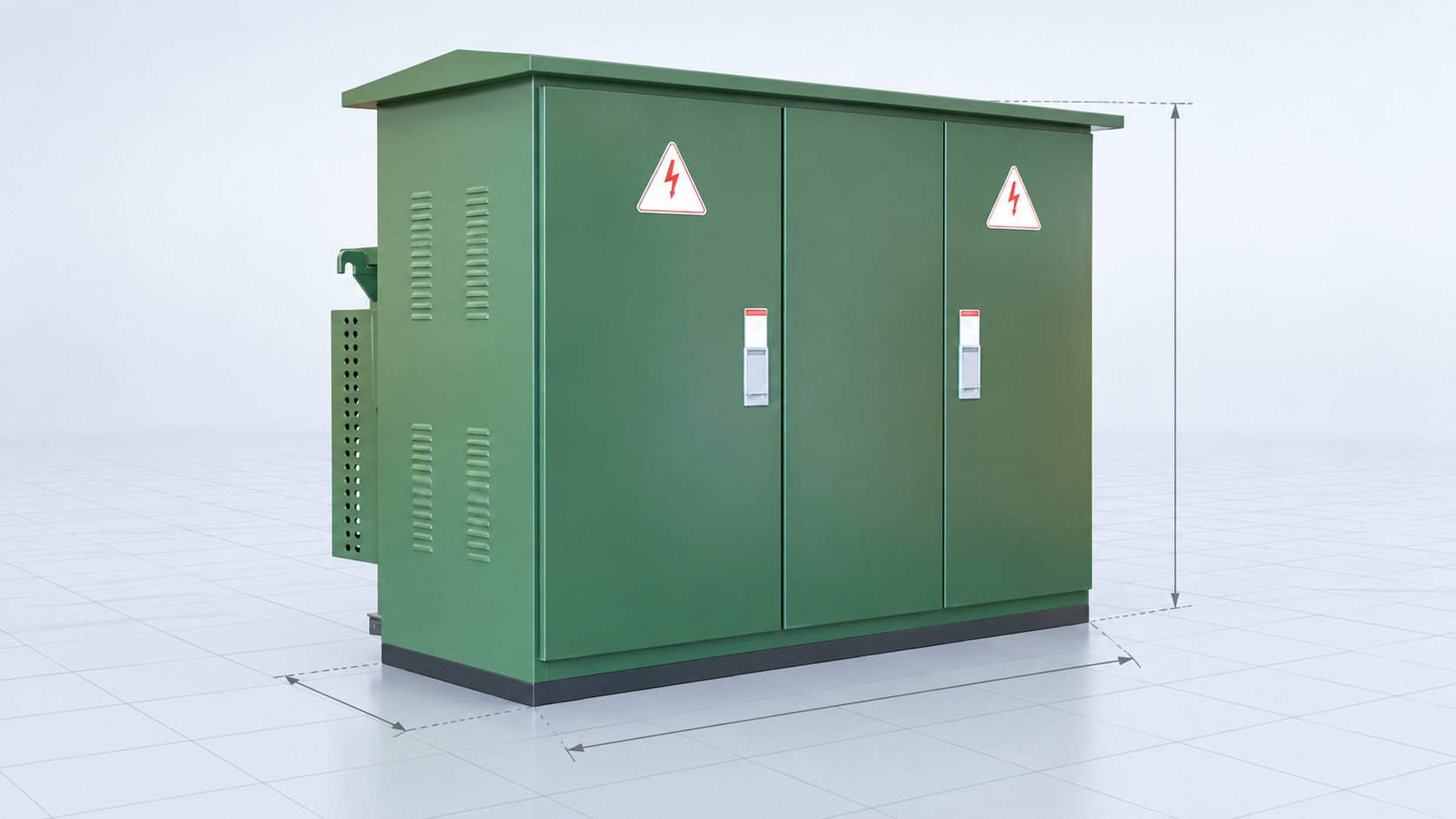
Substation construction converts engineering drawings into an energized asset through controlled civil work, equipment installation, cabling, testing and handover. A successful project manages interfaces between contractor, utility, equipment suppliers and commissioning team from the start. This guide covers construction sequence, quality records, pre-commissioning, energization and lifecycle maintenance.
Preconstruction Planning
Freeze the design basis, single-line, layout, protection philosophy and major equipment interfaces before site work. Complete surveys, geotechnical investigation, soil resistivity, environmental permits and utility approvals. Develop the construction execution plan, safety plan, inspection/test plan, temporary-power plan and energization strategy.
Long-lead equipment drawings must be integrated with foundations, transport routes, cable trenches and control-room openings. A small interface mismatch can delay delivery or require destructive rework.
Typical Construction Sequence
- Site clearing, grading, drainage and temporary access.
- Earth-grid installation and test points.
- Foundations, oil bunds, trenches, ducts and buildings.
- Structures, fences, roads and fire systems.
- Transformer, switchgear and primary equipment installation.
- Bus conductors, power cables, control cables and bonding.
- Protection, control, SCADA and auxiliary systems.
- Pre-commissioning, integrated testing and energization.
Quick Comparison and Selection Table
Use this table as a quick review of the main engineering and procurement decisions explained in the article.
| Decision area | Practical meaning | What to verify |
|---|---|---|
| Preconstruction Planning | Freeze the design basis, single-line, layout, protection philosophy and major equipment interfaces before site work. | Complete surveys, geotechnical investigation, soil resistivity, environmental permits and utility approvals. |
| Civil and Grounding Quality | Verify foundation dimensions, level, anchor positions, concrete strength and embedded items against approved vendor drawings. | Cable trenches need correct slope, drainage, covers, fire stopping and segregation. |
| Receiving and Storing Equipment | Inspect shipping damage, shock/tilt indicators, seals, pressure, oil level and packing lists. | Store bushings, relays, mechanisms and accessories under manufacturer conditions. |
| Power Transformer Installation | Confirm transport route, foundation and lifting plan. | Large units may require accessory assembly, vacuum treatment, oil filling and leak testing. |
| Switchgear Installation | Check floor flatness, lineup datum and fixing points. | Align shipping sections without forcing bus joints. |
Civil and Grounding Quality
Verify foundation dimensions, level, anchor positions, concrete strength and embedded items against approved vendor drawings. Cable trenches need correct slope, drainage, covers, fire stopping and segregation. Transformer bunds and drainage must meet oil-containment requirements.
Install the earth grid before final surfacing and record conductor routes, joints and test points. Inspect welds or connectors, measure continuity and preserve as-built coordinates. Grounding conductors should not be damaged by later excavation.
Receiving and Storing Equipment
Inspect shipping damage, shock/tilt indicators, seals, pressure, oil level and packing lists. Store bushings, relays, mechanisms and accessories under manufacturer conditions. Apply heaters or desiccants where required and maintain preservation records. Delivery acceptance does not replace installation inspection.
Power Transformer Installation
Confirm transport route, foundation and lifting plan. Large units may require accessory assembly, vacuum treatment, oil filling and leak testing. Check core/tank grounding, radiators, conservator, bushings, tap changer, marshalling cabinet and cooling. Oil samples and electrical baseline tests should be completed before energization.
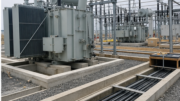
LBAJI’s 35 kV oil-immersed transformer should be installed using approved lifting, oil and test procedures. Packaged projects can reduce site interfaces with a 35 kV new-energy box substation or YBM-12 prefabricated substation.
Switchgear Installation
Check floor flatness, lineup datum and fixing points. Align shipping sections without forcing bus joints. Clean and assemble busbars using specified surface preparation, hardware and torque. Verify shutters, breaker racking, earthing switches and interlocks. Cable terminations require phase identification, stress control, support and minimum bend radius.
Control and Protection Cabling
Segregate power, CT/VT, control and communications cables as required. Confirm cable numbers, cores, shields, earth points and terminal torque. CT secondaries must never be left open during energized service. Point-to-point checks should trace every trip, close, alarm and interlock circuit.
Pre-Commissioning Tests
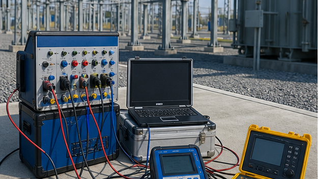
- Ground-grid continuity and resistance/touch-step verification as specified.
- Transformer ratio, vector group, winding resistance, insulation and oil tests.
- Breaker timing, contact resistance, insulation and mechanical operation.
- CT/VT ratio, polarity, excitation and secondary circuit checks.
- Power cable insulation, sheath and phase checks.
- Relay secondary injection and setting verification.
- Battery capacity, charger, DC distribution and trip-circuit tests.
- SCADA points, time synchronization, interlocking and communications.
Integrated Functional Testing
Individual relay pickup tests are not enough. Inject primary or simulated quantities through CT/VT circuits, prove relay logic, operate the correct breaker and verify indication at local panels and control center. Test transfer schemes, breaker failure, intertrips, lockouts, load shedding and communication loss states.
Energization Readiness
Close all punch-list items that affect safety or function. Approve as-built single-lines, settings, switching program, emergency plan and ownership boundaries. Confirm permits, clearances, grounds removed, tools accounted for, protection in service and communication available. Energize in defined stages and monitor voltage, current, noise, gas/oil and temperatures.
Maintenance Strategy
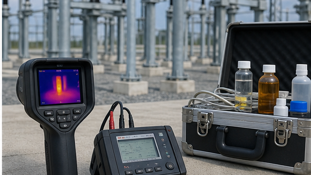
Combine time-based tasks with condition data and operating duty. Transformer monitoring may include dissolved gas, oil quality, temperature, moisture and bushings. Switchgear maintenance includes mechanisms, contact resistance, timing, insulation, relays and interlocks. Thermography, partial discharge and battery tests identify developing problems. For the recurring inspection program after handover, use the substation maintenance checklist and procedures.
Contractor and Supplier Handover
Handover should include approved as-built drawings, calculations, settings files, test reports, certificates, operation manuals, spare parts, special tools, training and warranty contacts. Record open warranty items and baseline condition data. Digital files should use controlled versions and remain retrievable for future modifications.
Selecting Substation Construction Contractors
Evaluate demonstrated experience at the voltage level, safety performance, qualified personnel, testing capability, quality system, schedule resources and local licensing. Require a clear responsibility matrix for design, procurement, civil work, installation, protection settings, utility interface and energization.
Turnkey substation construction scope
A complete construction scope connects survey and civil work with grounding, structures, primary equipment, control panels, cables, communications and utility interfaces. Responsibility boundaries for design, supply, installation, testing and energization should be explicit so no interface is left between contractors.
Quality records needed before energization
The handover package should contain approved drawings, material records, torque and inspection sheets, test reports, relay settings, logic results, punch-list closure, operating procedures and as-built documents. Energization readiness is an evidence review, not simply confirmation that equipment is physically installed.
Technical references and further reading
The following independent sources support the standards, terminology, calculations, and safety context discussed in this guide:
- IEEE C37.121 guide for unit substations — IEEE guidance on coordinating incoming, transformer, transition, and outgoing sections in unit substations.
- OSHA electric power transmission and distribution overview — Official safety context for transmission and distribution systems and equipment.
- Electrical substation overview — A general reference for substation functions, types, switching, protection, and transformation.