Switchgear seismic qualification is evidence that a defined equipment configuration meets specified earthquake-related performance requirements under stated installation conditions. It involves more than choosing stronger anchor bolts or obtaining a generic certificate. The project must connect its seismic demand, required equipment function, qualification evidence and installed support arrangement. This guide helps buyers organize that review without claiming that a standard cabinet photograph proves seismic performance or prescribing an anchorage design for an unknown structure.
Begin with the required function
Define what the switchgear must do during and after the specified event. Structural stability, avoidance of hazardous displacement and continued electrical function are related but distinct objectives. The project engineer should identify the applicable performance requirements and acceptance basis. A statement that equipment remained standing does not by itself establish that every required switching or protection function remained available.
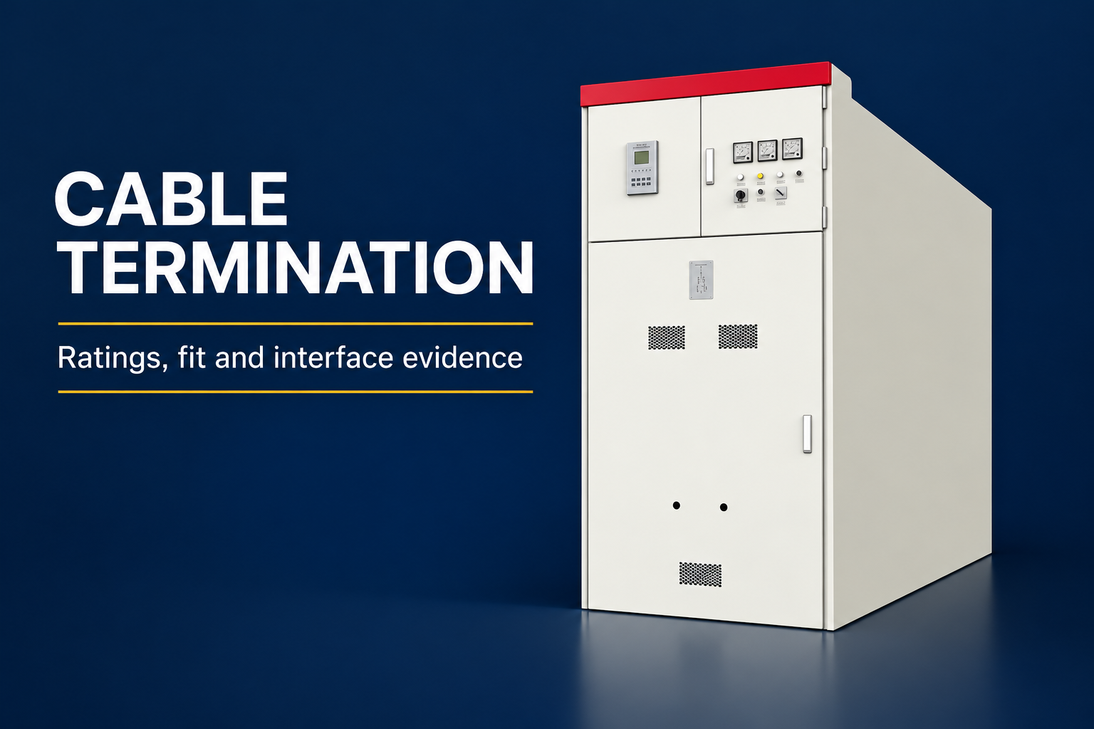
The LBAJI GGD lineup shown here is a real product exterior reference. Its doors, meters and cabinet sections can be identified visually, but the image provides no earthquake qualification, internal bracing detail or anchor specification. Request evidence for the exact offered configuration and the project installation conditions before describing an assembly as qualified.
Establish the project seismic demand
The equipment review needs the project’s defined seismic design information, including the installation location within the building or facility and the applicable requirements. Equipment at different elevations or on different supporting structures may face different demands. A ground-level site description alone may not provide everything needed for the equipment and anchorage assessments.
Assign responsibility for translating the building design basis into equipment requirements. The structural designer, electrical designer, equipment supplier and installer should understand which information each must provide. Avoid asking a manufacturer to approve an undefined location or assuming that the electrical equipment supplier has independently designed the building support beneath the lineup.

Understand the scope of qualification evidence
Qualification evidence should identify the equipment tested or assessed, its configuration and the conditions covered. Relevant details can include cabinet dimensions, section arrangement, mass distribution, installed devices, supports and mounting configuration. A brochure phrase such as earthquake resistant cannot replace the report and the declared scope that make the claim assessable.
The IEC 60068-3-3 catalogue describes guidance on seismic testing for equipment. It is useful for understanding the test-document scope, while the complete applicable requirements and project acceptance criteria still need review. Do not treat the name of a test standard as a universal certificate that automatically covers every configuration or installation method.
Reference context: IEC 60068-3-3 seismic test methods for equipment scope. This original qualitative checklist organizes project decisions; it is not a reproduced standard or a substitute for approved criteria.
| Evidence area | Question to resolve | Record to request |
|---|---|---|
| Required performance | Which functions must be retained during or after the event? | Project performance and acceptance requirements |
| Seismic demand | What demand applies at the equipment support location? | Approved project design basis |
| Equipment identity | Does the offered lineup match the qualified configuration? | Report identification and configuration comparison |
| Mounting | Are base, support and fixing conditions within the evidence scope? | Qualified mounting details and installation instructions |
| Building interface | Can the supporting structure transfer the specified loads? | Project structural design and coordination approval |
| Completion | Was the installed assembly built as approved? | Inspection records, changes and as-built drawings |
Compare the offered assembly with the evidence
Prepare a configuration comparison rather than accepting a report solely because the model family name is similar. Identify section count, dimensions, installed components and mounting arrangement. Ask the responsible technical organization to explain any differences and the basis for extending the evidence to the actual order. Keep that explanation with the technical approval package.
Changes that seem commercially minor can alter the configuration being evaluated. Additional compartments, different device masses, changed door equipment or a new base arrangement may need review. This does not mean every difference invalidates qualification; it means the buyer should obtain an explicit, competent assessment rather than inventing a rule for acceptable similarity.
Distinguish anchorage from equipment performance
Anchorage transfers equipment forces into the supporting structure. The cabinet, its internal components, connections and functional systems also have performance requirements. Installing larger anchors does not independently prove that the enclosure or internal equipment is suitable. Treat these as connected scopes with clear responsibility and a common project design basis.
The anchorage package should coordinate the actual base arrangement, support condition, equipment loads and structural substrate. A designer must consider the complete load path and installation constraints. This article intentionally gives no bolt diameter, embedment depth or universal spacing: those choices require the project design, applicable requirements and approved product information.

Review the supporting structure and base
Confirm whether the lineup rests directly on a concrete slab, a steel frame, a housekeeping pad or another support. The support’s properties and connections form part of the installation boundary. A qualified mounting arrangement cannot simply be transferred to a visibly different base without confirming that the evidence and project design still apply.
Coordinate leveling, grout or other interface provisions through approved details where applicable. Record tolerances and inspection requirements supplied for the installation. A cabinet may appear level from the front while the completed support differs from the assessed arrangement. Acceptance should use the specified measurements and records rather than a photograph alone.
Coordinate cables and connected services
Cable systems, conduits and other connected services can restrain or load the equipment during movement. Their arrangements should be coordinated with the switchgear and building design. Identify which party reviews relative movement, support locations and connection interfaces. A cabinet anchorage detail does not automatically settle these external connections.
Preserve the required electrical and enclosure functions at those interfaces. Avoid introducing unapproved modifications merely to obtain a convenient cable route or bracket location. If the installation changes an entry opening, support point or compartment arrangement, obtain the corresponding equipment and structural review before accepting the completed assembly.
Plan installation inspections before delivery
An inspection plan should identify the approved documents, responsible personnel and hold points for the mounting and support arrangement. Some features may become difficult to inspect after adjacent equipment or cables are installed. Agree when evidence must be collected, what measurements are required and who may release the next stage of work.
Keep equipment identity traceable throughout installation. Record delivered section references, approved mounting parts and any field changes. Where the project requires particular installer qualifications or inspections, include those in the procurement and construction scope. Leaving them until handover can create a gap between the assumed qualified installation and what was actually built.

Read reports for limitations and acceptance criteria
A useful review asks what was evaluated, how performance was judged and what conditions or exclusions apply. The answer should be specific enough to connect the report to the proposed order. A certificate cover page can be a starting point, but the underlying report and instructions usually contain the information needed to evaluate applicability.
Distinguish evidence of mechanical response from evidence of required electrical function. Identify whether the qualification addresses operation during the event, checks afterward or another defined condition. Avoid rewriting a limited report conclusion into a broader promise of uninterrupted service. The accepted claim should match the report and the project’s required performance.
Handle substitutions through change control
Create a review trigger for changes to the lineup, mounted devices, support arrangement and site anchorage details. A procurement substitution should not bypass qualification review because its electrical rating looks equivalent. Document the proposed difference, the technical assessment and any revised installation or inspection requirements before approving the change.
Use the same discipline for field modifications. Unplanned brackets, drilled holes or moved supports can affect more than the installation appearance. Keep the original evidence and the approved revision together so future maintainers understand the accepted configuration. Do not silently replace a drawing and lose the reason the change was considered acceptable.
A procurement example
Consider two quotations for the same electrical duty. One includes a qualification report for a defined lineup and installation arrangement; the other provides only a general seismic statement. Before comparing prices, issue a common project requirement and request the second bidder’s evidence, scope and mounting conditions. Also confirm whether the first offer actually matches the proposed order.
The resulting comparison should cover documentation, configuration, structural coordination, installation obligations and inspection costs. Neither a thick report nor a low price settles applicability by itself. A concise compliance schedule with linked evidence makes the unresolved boundaries visible and allows the responsible engineers to approve a technically comparable equipment package.
Handover and subsequent changes
Retain the project demand information, accepted qualification evidence, configuration comparison, mounting instructions, structural approval and installation records in one traceable handover package. Operators should know where to find restrictions relevant to future changes. The qualification record loses practical value if it cannot be connected to the equipment actually installed.
After significant alterations or a relevant event, follow the project’s inspection and engineering review requirements before making claims about continued suitability. Normal operation after an event is useful information but does not replace the required assessment. The appropriate response depends on the equipment, observed condition and applicable procedures, rather than a generic promise in an article.
Frequently asked questions
Does seismic qualification mean the equipment will operate through any earthquake?
No. Qualification has a defined demand, configuration, performance objective and installation scope. The accepted claim must remain within those stated conditions.
Are stronger anchor bolts enough to qualify a switchgear lineup?
No. Anchorage, supporting structure, cabinet response, internal components and required electrical function need coordinated assessment. Bolt selection alone does not establish equipment performance.
Can a report for a similar cabinet model be accepted automatically?
No. Obtain a configuration comparison and a competent assessment of differences. Similar model names or exterior appearance do not independently establish that the evidence applies.
Who designs the building support for the switchgear?
The project must assign that responsibility to the appropriate structural design organization and coordinate it with equipment information. It should not be assumed to be included in an undefined supplier scope.
Do the GGD illustrations show certified seismic mounting details?
No. They show the real product exterior only. Use the approved qualification, structural and installation documents for the actual order; the illustrations provide no anchor design or certification claim.
Technical sources and related equipment
Standard catalogue pages establish document scope; compliance and acceptance require the applicable full documents and project engineering review.
- IEC 60068-3-3 seismic test methods for equipment scope
- IEC 61439-1 low-voltage assembly scope
- FEMA E-74 electrical equipment anchorage guidance; historical background, not current project code
- LBAJI GGD Low-Voltage Switchgear
- switchgear equipment fundamentals
- switchgear verification and testing
- switchgear maintenance checklist
Further learning: equipment functions
This independent educational introduction explains the equipment background. It does not demonstrate a safe work procedure for the specific assembly. Source: Gaurav J – TheElectricalGuy.
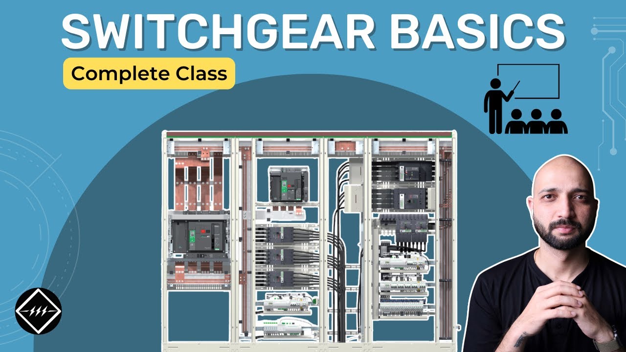
Watch Switchgear Basics: Complete Beginner's Guide | TheElectricalGuy