Distribution transformer sizing turns connected load, operating diversity, and power factor into a defensible kVA rating before you solicit quotations.
Specifiers who skip structured kVA calculation often oversize equipment, underestimate voltage regulation, or miss harmonic and motor-starting effects. This guide outlines a practical workflow for industrial and commercial feeders—not a substitute for your licensed engineer of record.
Gather meter data, single-line diagrams, and growth assumptions before applying the steps below.
Contents
- Part 1. Inputs you need before calculating kVA
- Part 2. kVA calculation methods
- Part 3. Diversity, coincidence, and future load
- Part 4. Power factor, harmonics, and margin rules
- Part 5. From calculated kVA to RFQ-ready specification
- Part 6. Product recommendation and Fit Boundary
- Part 7. Common sizing mistakes
Part 1. Inputs you need before calculating kVA
Start with a connected-load inventory by feeder: lighting, HVAC, motors, drives, and process loads.
Record operating schedules—coincident demand usually determines sizing, not the sum of nameplate ratings.
Collect existing power factor, THD where available, and motor starting methods (DOL, soft start, VFD).
Define primary and secondary voltage, vector group and tap range targets, short-circuit impedance goals, and any utility interconnection limits.
For related context, see the loading guide for oil immersed transformers.
For related context, see the how much load a 63 kVA transformer can handle.
Part 2. kVA calculation methods
Method A — summation with diversity: Add connected kVA by group, apply diversity factors from your load study, and convert to three-phase kVA using ( \text{kVA} = \frac{\text{kW}}{\text{PF}} ) for each coincident block.
Method B — measured demand: Use interval meter data (15–30 minute peaks) over representative seasons; multiply by appropriate growth and margin factors.
Method C — motor-heavy feeders: Include starting kVA or motor contribution per your protection study—not steady-state motor nameplate alone.
| Step | Action | Output |
|---|---|---|
| 1 | List connected loads by feeder | Connected kVA table |
| 2 | Apply diversity / coincidence | Coincident kVA |
| 3 | Adjust for power factor | Required kVA |
| 4 | Add engineering margin | Preliminary nameplate kVA |
| 5 | Map to standard kVA tier | RFQ kVA rating |
Compare no-load and load losses only after the preliminary kVA band is set.
Part 3. Diversity, coincidence, and future load
Campuses and industrial plants rarely operate all loads simultaneously.
Document which loads are mutually exclusive and which peak together.
Add explicit growth margin for planned expansions—retrofitting tap or parallel feeders is costlier than modest upfront headroom when growth is credible.
Part 4. Power factor, harmonics, and margin rules
Low power factor increases current for the same real power; size on kVA demand, not kW alone.
Harmonic-rich environments may require study before final kVA approval—record THD at the point of common coupling when drives dominate.
Typical engineering margins vary by code and owner policy; state your margin rule in the RFQ rather than leaving it implicit.
Part 5. From calculated kVA to RFQ-ready specification
Translate calculated kVA into a standard catalog tier (e.g., 500, 630, 800, 1000 kVA) without jumping two steps unless growth proof exists.
Attach the calculation summary, single-line diagram, and protection assumptions to the RFQ.
Request impedance suitable for your fault study and document required cooling method and enclosure.
Rated kVA and voltage combination should appear on the issued nameplate and match the approved single-line diagram.
Part 6. Product recommendation and Fit Boundary
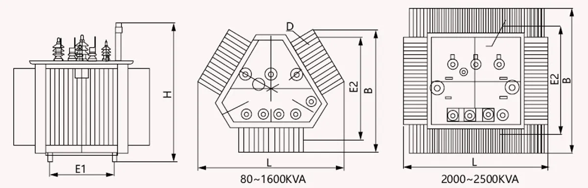
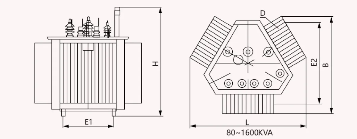
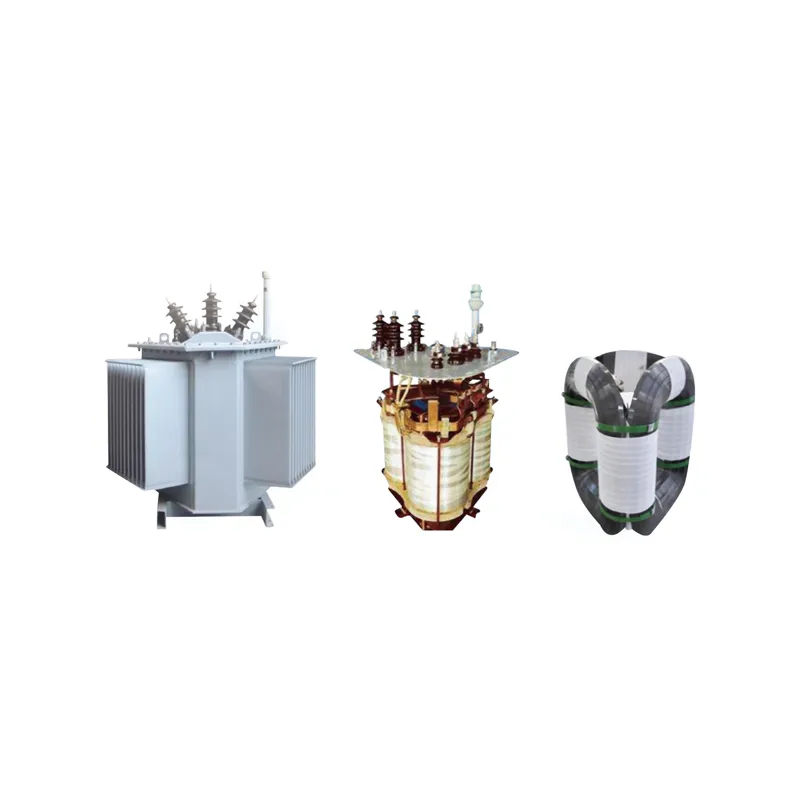
Product recommendation: After kVA band selection, review the transformer product category and match cooling class to site—S□-M oil-immersed power transformer series for oil immersed distribution ratings or SC(B) resin insulated dry transformer series for dry type indoor applications.
| Better fit | Poor fit without extra study |
|---|---|
| Projects with documented load study and growth plan | Guesswork from rule-of-thumb amps only |
| Teams supplying SL diagram and protection data | PO at minimum catalog kVA without margin review |
| Buyers comparing standard kVA tiers with loss data | Single vendor marketing kVA without calculation |
Submit calculated kVA, voltage class, cooling preference, and test requirements through Contact Us for catalog confirmation.
Part 7. Common sizing mistakes
- Sizing from connected kW without diversity or power factor adjustment.
- Ignoring motor starting or harmonic content on industrial feeders.
- Selecting the next catalog kVA two steps above calculated demand without justification.
- Mixing single-phase and three-phase loads without proper aggregation.
- Omitting altitude or ambient derating in the RFQ after calculation.
- Treating temporary construction load as permanent nameplate basis.
FAQ
What is the difference between kW and kVA for sizing?
kW is real power; kVA includes reactive and harmonic components. Transformers are rated in kVA, so convert using power factor and load type.
Should I size to peak or average demand?
Size to coincident peak demand over your study interval, then apply an agreed engineering margin—not instantaneous anecdotal peaks alone.
How much margin is typical?
Margin depends on owner policy and growth certainty; document your rule in the calculation appendix rather than hiding margin in vendor quotes.
Do I need a formal load study?
Motor-heavy, harmonic-rich, or multi-building campuses benefit from metered studies; small uniform loads may use summation with conservative diversity.
How do standard kVA tiers affect sizing?
Round up to the next standard tier that meets calculated demand plus margin; avoid oversizing two tiers without load growth evidence.
When should harmonics change the selected kVA?
When THD or non-linear share is high, confirm with a study—do not rely on nameplate kVA alone without harmonic consideration.
What should I send suppliers after sizing?
Send calculated kVA, voltage combination, vector group, cooling class, impedance target, and required test documents with your single-line diagram.