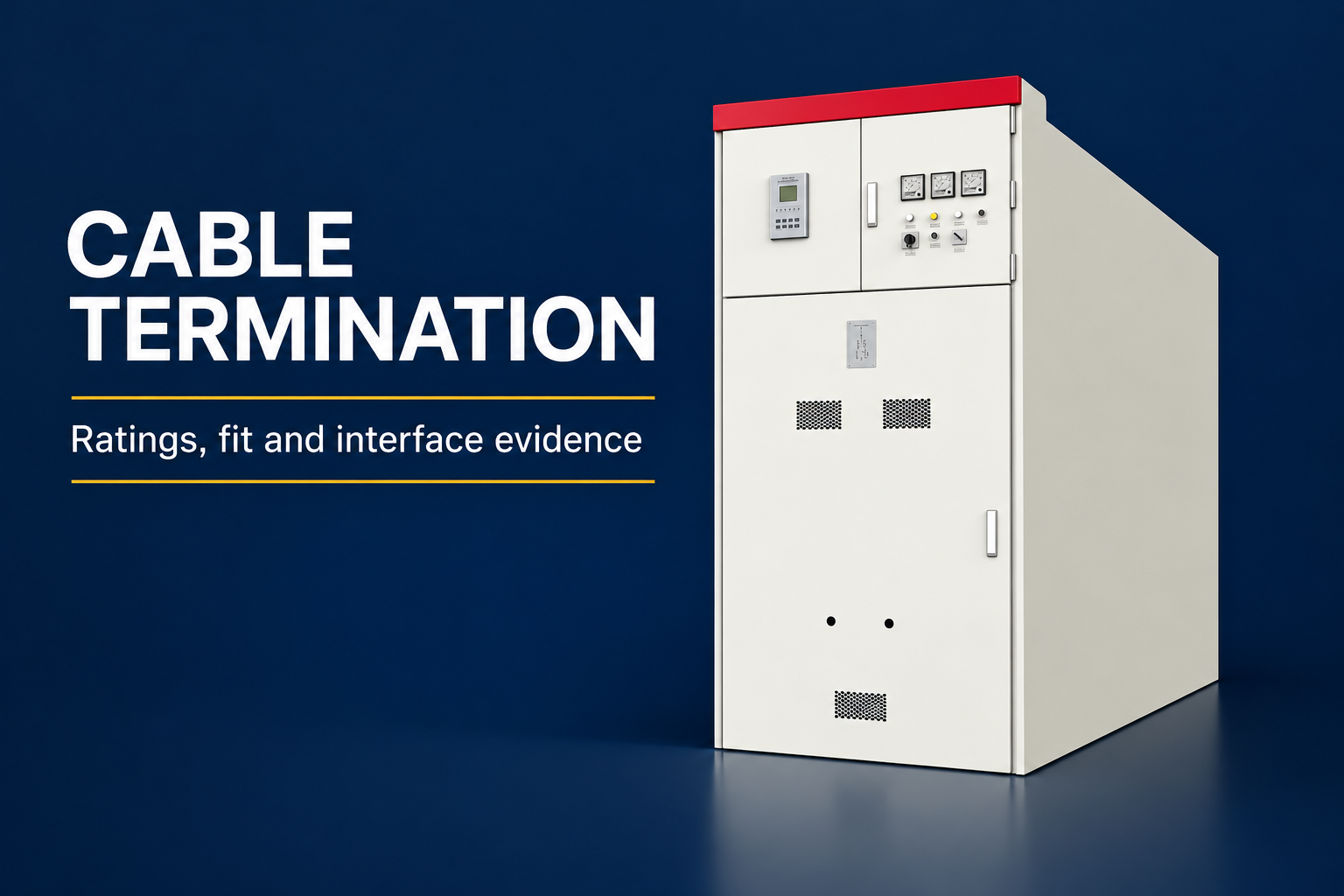
Parallel operation of transformers doubles capacity and adds redundancy—when the units match. When they do not, circulating current quietly burns margin and money.
Planners deciding between one large unit and two paralleled units need the matching conditions, the load-sharing math, and the boundaries where paralleling stops making sense. This guide covers all three.
Gather nameplate data for every unit involved—existing and new—before planning.
Part 1. When paralleling enters the plan
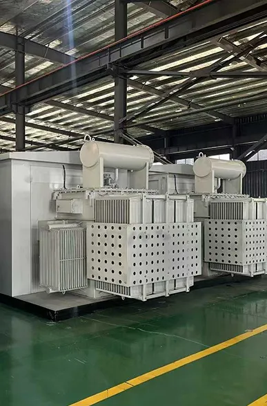
Parallel operation appears in three situations: staged capacity growth, redundancy requirements, and connecting a new unit beside a legacy one.
Each situation shares the same physics but different constraints—the legacy case is hardest because its parameters are already fixed.
For related context, see the loading guide for oil immersed power transformers.
For related context, see the distribution transformer kVA calculation guide.
Part 2. Conditions for successful paralleling
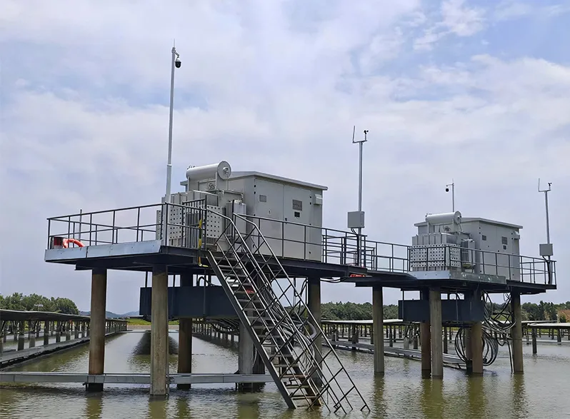
Five conditions decide whether two units can share a bus safely.
| Condition | Requirement | Consequence when violated |
|---|---|---|
| Vector group | Identical phase displacement (same clock number) | Phase-to-phase short through both units |
| Voltage ratio | Equal ratios on matching taps | Circulating current even at no load |
| Short-circuit impedance | Values within a few percent of each other | Unequal sharing; one unit overheats |
| Polarity and phase rotation | Verified consistent | Connection faults at closing |
| Tap positions | Coordinated during operation | Ratio mismatch reintroduced in service |
The rated kVA and voltage combination may differ between units within limits, but impedance and ratio matching decide how well capacity adds.
Part 3. Impedance match and load sharing
Paralleled units share load in inverse proportion to their impedance; the stiffer unit takes more.
A common planning boundary keeps impedance values within about ten percent of each other and size ratios modest—beyond that, effective capacity shrinks.
Run the numbers: two units nominally equal on paper can still share unevenly at extreme tap positions.
Part 4. Vector group and polarity
Only units with identical phase displacement parallel directly; Dyn11 pairs with Dyn11, never with Dyn5.
Verify vector group and polarity by test before first closing, not from nameplates alone—verification is a standard commissioning step.
Where displacement differs, interconnection happens upstream in the network, not on a shared LV bus.
Part 5. Taps, control, and operating boundaries
Off-circuit taps must sit on matching positions; on-load tap changers need a common control scheme—independent hunting between units creates circulating current.
Define the operating boundaries in writing: allowed tap spread, loading ceiling per unit, and the switching sequence for taking one unit out.
Protection must see each unit individually; shared protection hides a failing transformer behind its partner.
Part 6. Product recommendation and Fit Boundary
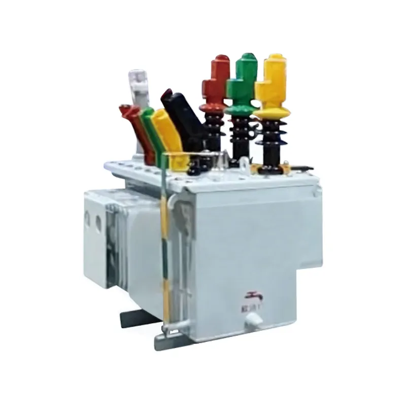
Product recommendation: Planning a matched pair is easier at series level, where impedance bands and vector groups are cataloged together. Start at the transformer product category, then review the S□-M oil-immersed power transformer series and the SC(B) resin insulated dry transformer series against the approved specification.
| Better fit | Poor fit without extra study |
|---|---|
| Projects matching new units to documented legacy data | Paralleling onto an undocumented legacy unit |
| Teams defining tap coordination and boundaries | Independent tap control without a scheme |
| Buyers stating paralleling intent in the RFQ | Ordering without declaring the paralleling plan |
Submit the rated kVA and voltage combination, vector group and tap range, no-load and load losses, cooling method and enclosure, and short-circuit impedance target through Contact Us for model-specific confirmation.
Part 7. Common paralleling mistakes
- Paralleling different clock numbers because voltages matched.
- Ignoring impedance spread and overloading the stiffer unit.
- Leaving tap changers uncoordinated across paired units.
- Sizing wildly unequal units and expecting arithmetic capacity.
- Skipping polarity verification at commissioning.
- Omitting the paralleling intent from the purchase specification.
FAQ
What conditions must transformers meet to run in parallel?
Identical vector group displacement, equal voltage ratios on matching taps, closely matched impedance, verified polarity, and coordinated tap control.
Can transformers with different vector groups operate in parallel?
Only if phase displacement is identical; different clock numbers on one bus create a short circuit through the windings.
How close must impedance values be for paralleling?
Planning practice keeps them within roughly ten percent; a wider spread shifts load onto the lower-impedance unit.
What happens when voltage ratios differ between units?
Circulating current flows even at no load, consuming capacity and heating both units.
Do tap changer positions need to match?
Yes—off-circuit taps on the same position, and on-load changers under a common control scheme.
Can different kVA sizes share load in parallel?
Within modest size ratios and matched impedance, yes—each carries load proportional to its rating when matching holds.
What paralleling data belongs in an RFQ?
The partner unit nameplate and test data, required impedance band, vector group, tap arrangement, and the intended operating scheme.