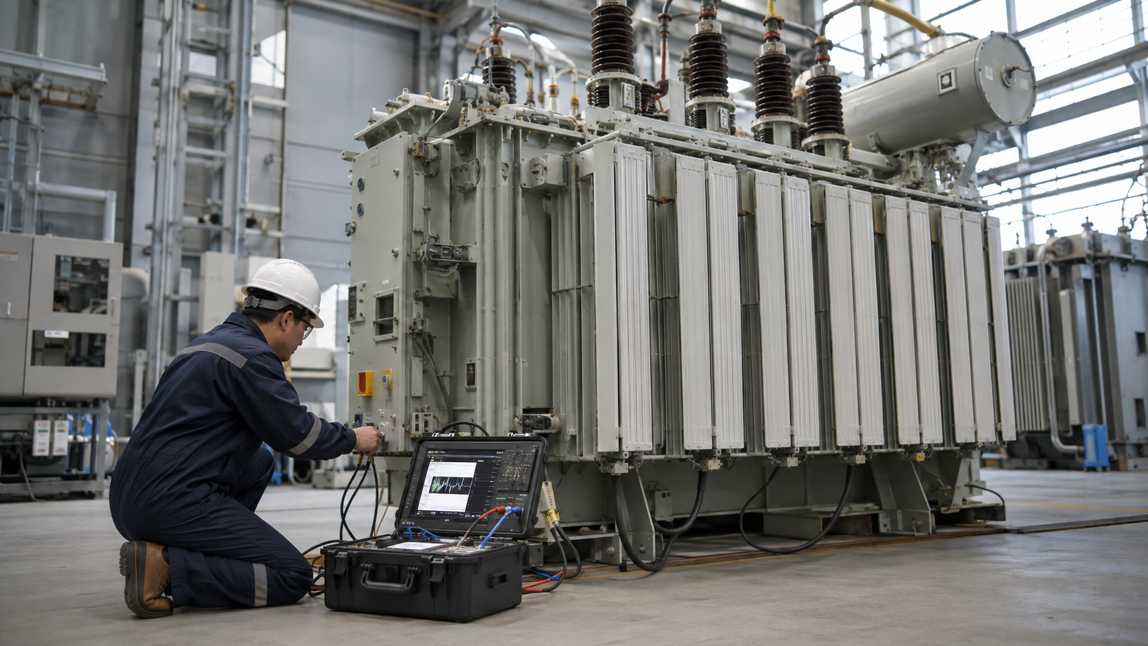
A transformer grounding system controls earth-fault current, stabilizes system voltage to earth and bonds exposed conductive parts for safety. It works together with differential, overcurrent, earth-fault, temperature, pressure and surge protection. This guide explains transformer neutral grounding, zigzag grounding transformers, tank bonding, protection zones, fire controls and commissioning.
System Grounding vs Equipment Grounding
System grounding connects a transformer neutral or derived point to earth, directly or through impedance. It determines earth-fault current and transient overvoltage behavior. Equipment grounding bonds the tank, radiators, structures, cable glands and enclosures to the protective-earthing network.
Both are necessary but serve different purposes. A grounded neutral does not replace tank bonding, and a bonded tank does not define the network’s neutral treatment.
Transformer Neutral Grounding Methods
Solid grounding
The neutral connects to earth with low impedance. Fault current is high, enabling sensitive and fast protection, but equipment experiences greater fault energy.
Resistance grounding
A neutral grounding resistor limits earth-fault current. High-resistance grounding may permit controlled operation for certain industrial systems; low-resistance grounding provides a defined higher fault current for selective tripping. The resistor needs current, time and insulation ratings.
Reactance grounding
A reactor limits fault current and influences transient performance. Its application requires system studies to avoid resonance and overvoltage issues.
Resonant grounding
An arc-suppression coil compensates network capacitive earth-fault current, reducing arcing-ground current. Tuning and fault detection require specialist design.
Quick Comparison and Selection Table
Use this table as a quick review of the main engineering and procurement decisions explained in the article.
| Decision area | Practical meaning | What to verify |
|---|---|---|
| System Grounding vs Equipment Grounding | System grounding connects a transformer neutral or derived point to earth, directly or through impedance. | It determines earth-fault current and transient overvoltage behavior. |
| Transformer Neutral Grounding Methods | The neutral connects to earth with low impedance. | Fault current is high, enabling sensitive and fast protection, but equipment experiences greater fault energy. |
| Transformer Tank and Earth-Grid Bonding | Provide robust connections from the transformer tank to the substation earth grid, often at more than one point according to the design. | Bond radiators, marshalling cabinets, neutral equipment, cable boxes, rails and metallic structures. |
| Zigzag Grounding Transformer | A zigzag grounding transformer creates a neutral on a delta-connected or otherwise neutral-less system. | Its interconnected windings present high impedance to balanced positive-sequence voltage but a controlled path for zero-sequence earth-fault current. |
| Differential Protection Considerations | CT ratios, polarity, class and saturation performance must suit maximum through-fault current. | The numerical relay compensates turns ratio and vector-group phase shift and uses harmonic restraint to remain stable during magnetizing inrush. |
Transformer Tank and Earth-Grid Bonding
Provide robust connections from the transformer tank to the substation earth grid, often at more than one point according to the design. Bond radiators, marshalling cabinets, neutral equipment, cable boxes, rails and metallic structures. Conductors must withstand fault current for clearing time and resist mechanical damage and corrosion.

Touch and step voltage—not resistance alone—determine personnel safety. The grounding study uses soil resistivity, fault-current split, grid geometry, surface layer and clearing time. Test continuity and grid performance after construction.
Zigzag Grounding Transformer
A zigzag grounding transformer creates a neutral on a delta-connected or otherwise neutral-less system. Its interconnected windings present high impedance to balanced positive-sequence voltage but a controlled path for zero-sequence earth-fault current. A neutral resistor or reactor may be connected at its neutral.
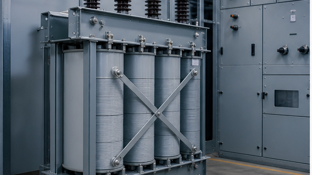
Specify system voltage, continuous neutral duty, earth-fault current and duration, insulation level, impedance, auxiliary load if any, enclosure and temperature rise. Protection must cover both winding faults and external grounding duty.
Main Transformer Protection Functions
- Differential protection: compares compensated currents around the transformer zone.
- Restricted earth fault: sensitive protection for earth faults near a grounded winding neutral.
- Overcurrent and earth fault: backup for external and internal faults.
- Buchholz relay: gas and oil-flow detection on conservator-type liquid transformers.
- Pressure relief/sudden pressure: detects or relieves internal pressure.
- Temperature: winding and oil temperature alarms/trips and cooling control.
- Oil level and cooling failure: mechanical condition alarms.
- Surge arresters: limit lightning and switching overvoltages.
Earth-fault schemes may use a core-balance current transformer (CBCT) to measure residual current around the circuit conductors. Review the CBCT working, wiring and relay-matching guide alongside the approved protection drawing.
Differential Protection Considerations
CT ratios, polarity, class and saturation performance must suit maximum through-fault current. The numerical relay compensates turns ratio and vector-group phase shift and uses harmonic restraint to remain stable during magnetizing inrush. Settings require transformer data and fault studies.
Fire and Physical Safety
Liquid-filled transformer design may require oil containment, fire separation, suppression or drainage under local rules. Maintain ventilation and safe clearances around dry-type units. Fences, locks, signage and barriers control access. Pressure-relief outlets must not discharge toward personnel routes.
Protection Coordination
Primary and secondary breakers or fuses must tolerate energization inrush and normal overload while protecting the transformer thermal and through-fault limits. Coordinate with downstream devices so external feeder faults do not unnecessarily trip the transformer incomer. For fuse-family guidance, see our transformer fuse guide. DGA trend analysis can add condition evidence but does not replace electrical protection coordination; see our transformer DGA monitoring guide.
A 35 kV oil-immersed transformer should be coordinated with upstream equipment such as KYN61-40.5 switchgear. Packaged projects using a 35 kV new-energy substation require the same grounding and protection study at system level.
Testing and Commissioning
- Verify transformer ratio, vector group and winding resistance.
- Check insulation, bushings, oil and grounding continuity.
- Confirm CT ratios, polarity and secondary earthing.
- Inject differential, earth-fault and overcurrent functions.
- Test temperature, gas, pressure and oil-level contacts.
- Prove alarms, cooling control and SCADA points.
- Trip each relevant breaker through the complete circuit.
Safe Operation
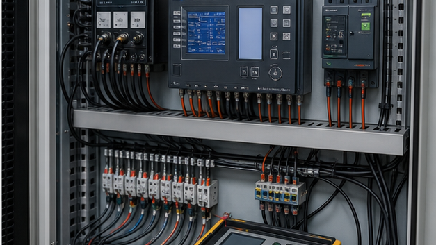
Transformer work requires isolation, lockout/tagout, absence-of-voltage verification, discharge, grounding and control of induced or backfeed sources. Neutral conductors and grounding resistors can remain hazardous during faults. Only qualified personnel should switch, test or maintain transformer systems. For a broader discussion of selecting diagnostic methods and recording results, see the transformer testing guide.
Zigzag and grounding transformers
A zigzag grounding transformer creates a neutral for a delta or otherwise ungrounded system while presenting high impedance to balanced positive-sequence current. Its rating depends on permissible ground-fault current and duration, not normal feeder kVA alone. A neutral resistor may be added to limit fault current.
Grounding versus bonding and core-ground testing
System grounding establishes the circuit reference; equipment bonding connects exposed conductive parts to the fault-return path. Large transformers also require controlled core grounding—usually a single intentional point. Multiple core grounds can cause circulating current and heating, so insulation and core-ground current tests support condition assessment.
Technical references and further reading
The following independent sources support the standards, terminology, calculations, and safety context discussed in this guide:
- IEC 60076-1 power transformer standard — Scope, terminology, ratings, connection symbols, testing, safety, and general requirements for power transformers.
- U.S. Department of Energy: Distribution Transformers — Official definitions, efficiency requirements, test procedures, and regulatory resources for distribution transformers.
- OSHA electric power transmission and distribution requirements — Safety requirements relevant to construction and work around electric power transmission and distribution equipment.