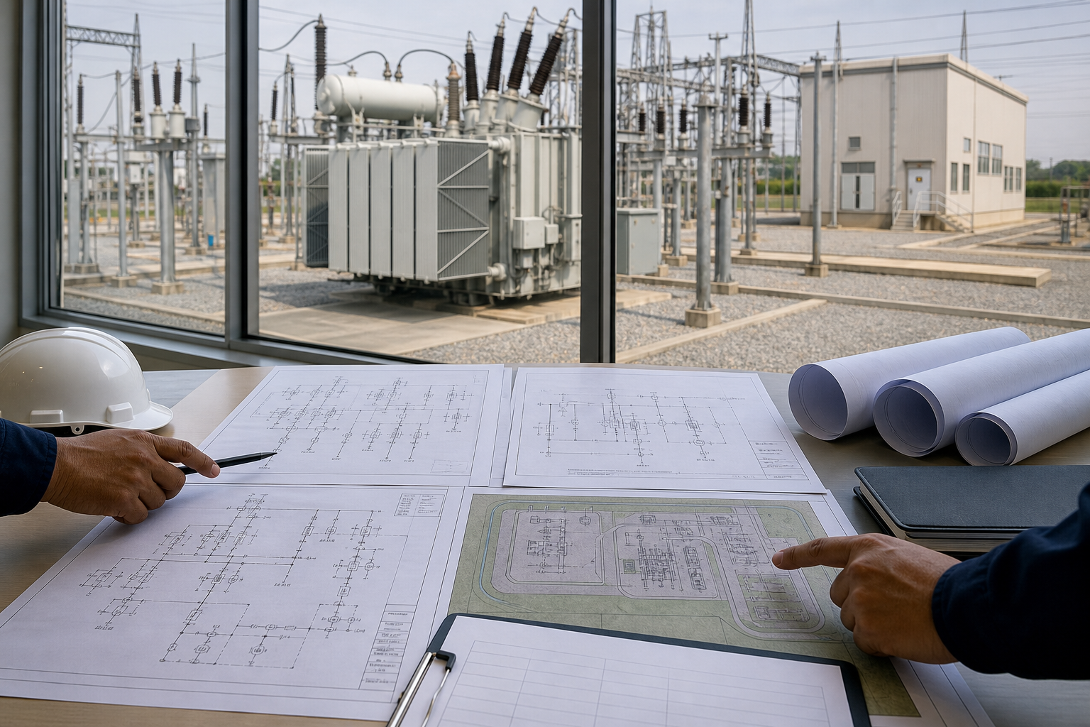
What is a substation? An electrical substation is a controlled point in a power system where electricity is transformed, switched, protected, measured, and routed. It connects generation and transmission networks to distribution feeders or large industrial loads. A substation is therefore more than a transformer: it is a coordinated system of primary equipment, protection, control, communication, grounding, and auxiliary power.
How does a power substation work?
Incoming lines first pass through surge protection, disconnectors, instrument transformers, and circuit breakers according to the arrangement. Busbars collect and distribute power among circuits. A power transformer changes voltage, while outgoing feeders carry electricity to the next network level or to customers.
Current and voltage transformers provide scaled signals to meters and protection relays. When a relay detects an abnormal current, voltage, frequency, temperature, or differential condition, it sends a trip command to the appropriate circuit breaker. Supervisory systems report status and measurements to operators locally and at a remote control center.
Main equipment in an electrical substation
- Power transformers raise or lower voltage and provide the required winding connection.
- Circuit breakers interrupt normal load and fault current.
- Disconnectors and earthing switches create visible isolation and safe maintenance conditions.
- Busbars connect incoming, transformer, coupler, and feeder bays.
- Instrument transformers supply measurement and protection signals.
- Surge arresters limit lightning and switching overvoltages.
- Protection and control panels identify faults, operate breakers, record events, and communicate.
- Station service, batteries, and chargers keep control and tripping functions available during an AC outage.
Quick Comparison and Selection Table
Use this table as a quick review of the main engineering and procurement decisions explained in the article.
| Decision area | Practical meaning | What to verify |
|---|---|---|
| How does a power substation work? | Incoming lines first pass through surge protection, disconnectors, instrument transformers, and circuit breakers according to the arrangement. | Busbars collect and distribute power among circuits. |
| Common substation types | A transmission substation connects high-voltage lines, changes transmission voltage, or sectionalizes the grid. | A distribution substation reduces subtransmission voltage to feeder voltage for local networks. |
| Protection, control, and grounding | Substation protection divides the network into zones so the smallest practical section is isolated during a fault. | Transformer differential, busbar differential, line distance, overcurrent, earth-fault, breaker-failure, and thermal functions may be applied according to voltage and importance. |
| From incoming line to outgoing feeder | In a typical distribution substation, an incoming line is switched by equipment such as 40.5 kV metal-enclosed switchgear . | The transformer reduces voltage, and the secondary feeds a bus through main switchgear. |
| Substation engineering priorities | Designers evaluate load forecasts, voltage levels, short-circuit duty, insulation coordination, reliability criteria, equipment ratings, protection selectivity, grounding, fire separation, access, drainage, noise,… | The final arrangement must be safe to operate as well as electrically correct. |
Common substation types
Transmission and distribution substations
A transmission substation connects high-voltage lines, changes transmission voltage, or sectionalizes the grid. A distribution substation reduces subtransmission voltage to feeder voltage for local networks. Industrial substations serve factories, mines, data centers, and other major consumers with site-specific reliability and process requirements.
Indoor, outdoor, AIS, and GIS
Air-insulated substations use atmospheric air for external insulation and usually require more space. Gas-insulated switchgear places energized parts in grounded sealed enclosures, making it compact and protected from harsh environments. Indoor installations improve environmental control; outdoor yards are common where space is available.
Package and mobile substations
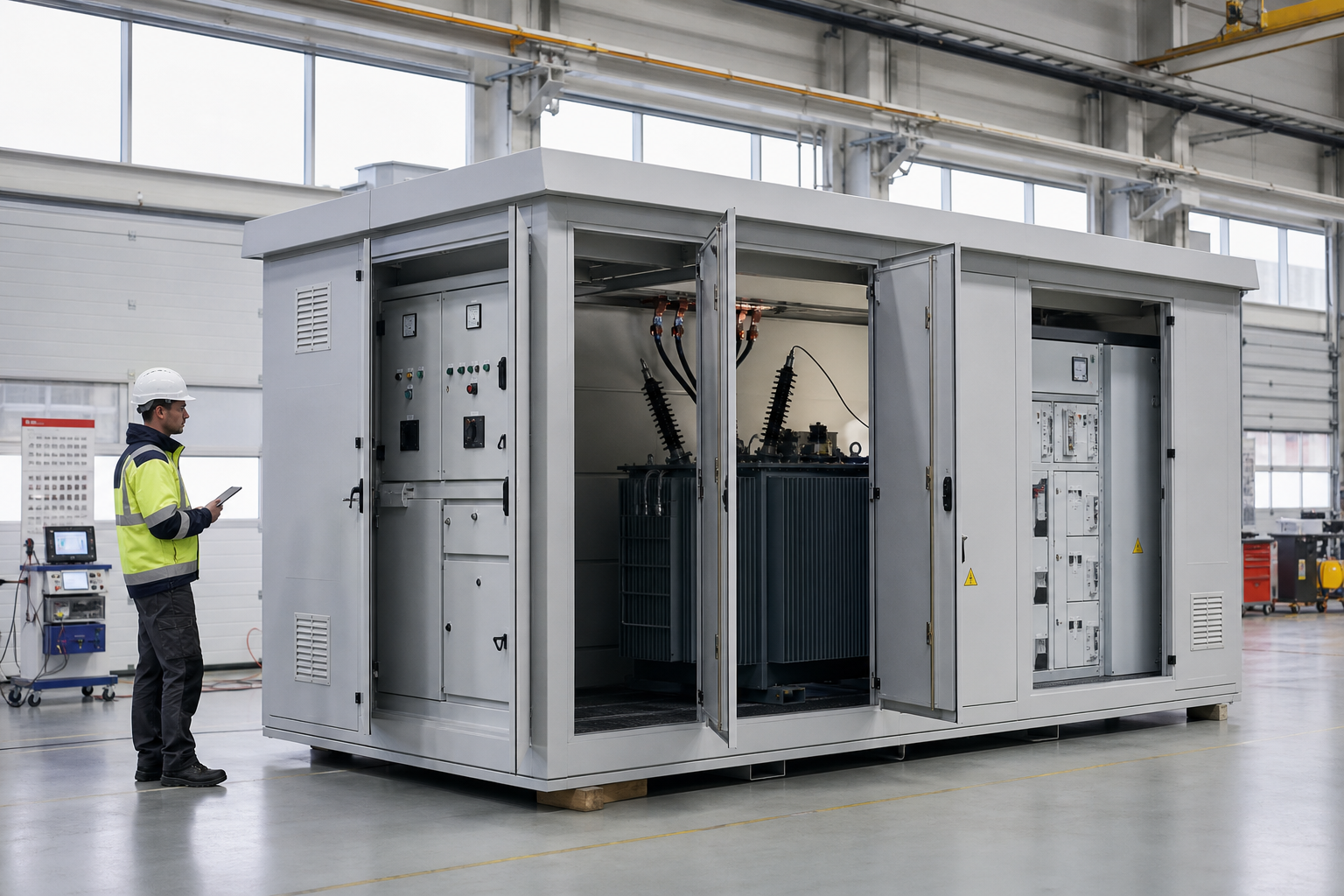
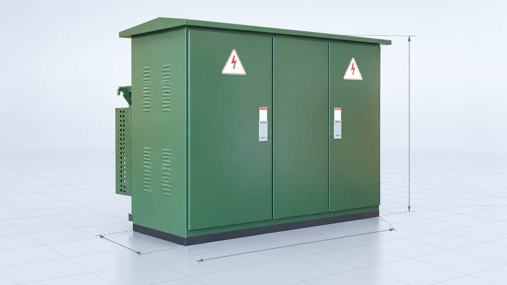
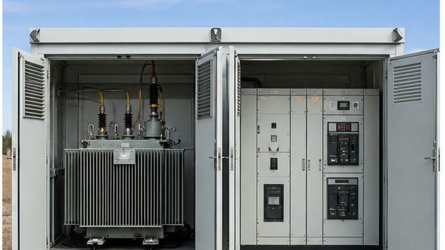
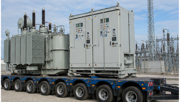
A prefabricated substation combines medium-voltage switchgear, a transformer, and low-voltage distribution in one coordinated enclosure. Mobile substations mount major equipment on trailers or skids for emergencies, planned maintenance, construction supply, and temporary load growth. For post-commissioning rounds and equipment-level task planning, use the substation maintenance checklist and schedule.
Protection, control, and grounding
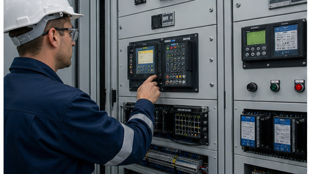
Substation protection divides the network into zones so the smallest practical section is isolated during a fault. Transformer differential, busbar differential, line distance, overcurrent, earth-fault, breaker-failure, and thermal functions may be applied according to voltage and importance. Redundant systems are used where a single failure cannot be allowed to prevent fault clearance.
The grounding grid limits touch and step voltage and provides a controlled path for fault and lightning current. Its design depends on fault current, clearing time, soil resistivity, geometry, and surface material. Grounding is integral to safety and relay performance, not an accessory added after the layout is complete.
From incoming line to outgoing feeder
In a typical distribution substation, an incoming line is switched by equipment such as 40.5 kV metal-enclosed switchgear. The transformer reduces voltage, and the secondary feeds a bus through main switchgear. Feeder breakers then distribute power to multiple circuits. Bus couplers and multiple transformers can provide maintenance flexibility and contingency capacity.
Substation engineering priorities
Designers evaluate load forecasts, voltage levels, short-circuit duty, insulation coordination, reliability criteria, equipment ratings, protection selectivity, grounding, fire separation, access, drainage, noise, communications, future expansion, and lifecycle maintenance. The final arrangement must be safe to operate as well as electrically correct.
What happens inside a substation during a fault
CTs and VTs continuously provide scaled measurements. A relay identifies an abnormal quantity and its protection zone, sends a trip signal, and the breaker interrupts current. Control systems report the event while disconnectors provide isolation after interruption. The ground grid carries fault current while limiting touch and step voltage.
Converter and industrial substations
Converter substations connect AC and DC systems or power-electronic processes. Industrial substations may combine utility supply, generators, motors and harmonic loads. Their protection, grounding, power quality and redundancy requirements differ from a simple distribution substation even though many primary components look similar.
Technical references and further reading
The following independent sources support the standards, terminology, calculations, and safety context discussed in this guide:
- IEEE C37.121 guide for unit substations — IEEE guidance on coordinating incoming, transformer, transition, and outgoing sections in unit substations.
- OSHA electric power transmission and distribution overview — Official safety context for transmission and distribution systems and equipment.
- Electrical substation overview — A general reference for substation functions, types, switching, protection, and transformation.