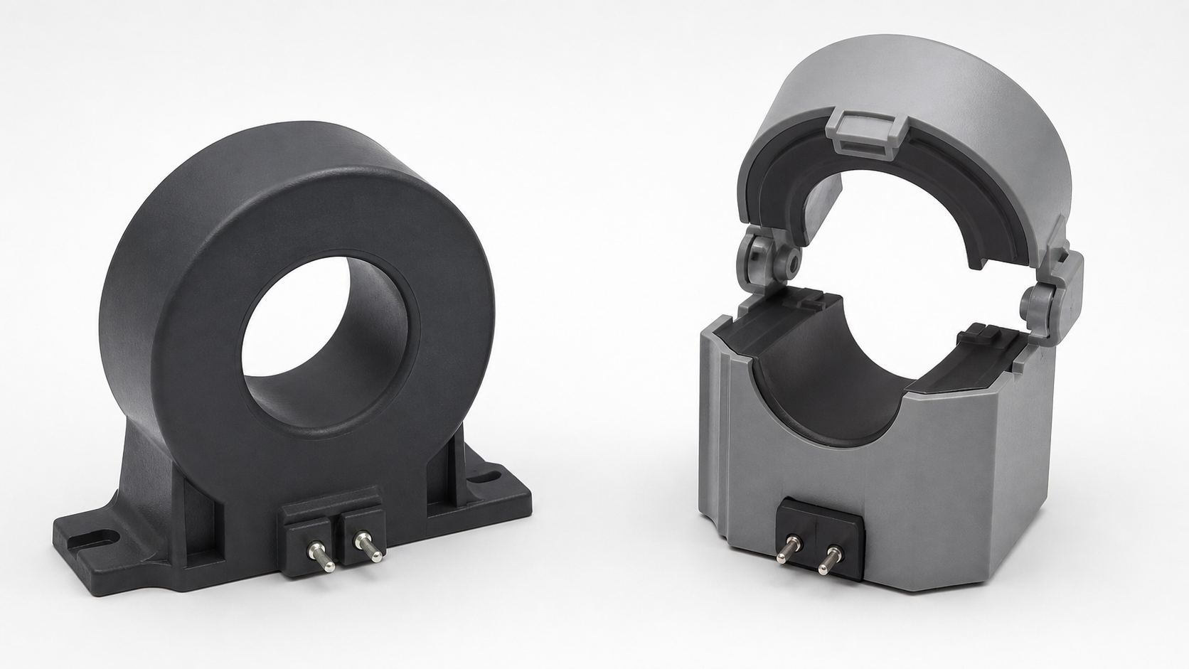
A core balance current transformer (CBCT) is a ring-type instrument transformer used to detect earth-leakage and ground-fault current. All live conductors of a circuit pass through one magnetic core. During normal operation, their instantaneous currents add to approximately zero, so the CBCT produces almost no secondary output. If current escapes to earth, the sum is no longer zero. The resulting residual magnetic flux produces a secondary signal for an earth-fault relay. Because it measures imbalance rather than load current, a correctly selected CBCT can detect much smaller ground faults than three conventional phase CTs connected residually.
| Question | Short answer |
|---|---|
| What does a CBCT measure? | The vector sum of the currents in every live conductor passing through its window. |
| What is it also called? | Zero-sequence CT, ring-type CT, window CT, or earth-leakage CT, depending on the market and application. |
| What does it protect against? | Earth leakage and phase-to-earth faults when paired with a compatible protection relay. |
| Does it measure normal load? | No. Balanced load current cancels magnetically; the output represents residual current. |
| Where is it installed? | Around all live conductors of one circuit, commonly at a cable termination inside switchgear. |
How a core balance current transformer works
The current-sum principle follows Kirchhoff’s junction rule, explained by OpenStax.
The operating idea is Kirchhoff’s current law expressed magnetically. Consider a three-phase, three-wire feeder. The three phase currents are displaced in time, but their vector sum is zero when the circuit is healthy:
IA + IB + IC = 0
Each conductor acts as a one-turn primary winding through the common toroidal core. The magnetic effects cancel, leaving negligible net flux. If insulation fails and some current returns through earth instead of another conductor in the window, the sum becomes a residual current (3I0 in symmetrical-component notation). That imbalance creates core flux and induces a current in the secondary winding. A relay compares the signal with its pickup setting and, after any intentional delay, alarms or commands a circuit breaker to trip.
For a three-phase, four-wire circuit, the neutral is a live conductor and normally passes through the same CBCT with all three phases. The protective earth conductor must not pass through the window. Otherwise, fault current returning in the PE conductor could cancel the imbalance the device is intended to detect. The exact arrangement must always follow the protection design and the equipment manufacturer’s instructions.
CBCT versus a conventional current transformer
A standard phase CT surrounds one conductor and reproduces a scaled version of that conductor’s current for metering or protection. A CBCT surrounds all conductors of one circuit and responds to their residual sum. Both are instrument transformers governed by the general current-transformer principles covered in IEC 61869-2, but their intended measurements are different.
| Feature | Core balance CT | Phase current CT |
|---|---|---|
| Primary conductors | All live conductors pass through one core | Normally one phase conductor per CT |
| Measured quantity | Residual or zero-sequence current | Individual phase current |
| Main purpose | Sensitive earth-fault protection | Metering, overcurrent, differential and other protection |
| Normal-load output | Ideally near zero | Proportional to phase load |
| Typical sensitivity | Optimized for relatively small leakage current | Selected for rated load and fault-current range |
Residual earth-fault protection can also be made from three phase CTs whose secondary currents are summed. However, small ratio and phase errors in the three CTs can create spill current even when no primary ground fault exists. A single CBCT performs the summation in one core and can therefore offer better sensitivity and stability for low-level earth faults. Phase CTs remain necessary when the relay also needs individual phase-current information.
Where CBCTs are used
CBCTs are common on motor feeders, generators, transformers, capacitor banks, building incomers and outgoing cables. They are particularly useful where an insulation failure must be detected before it grows into a high-current fault. Typical applications include:
- Motor protection: detecting winding-to-frame or cable earth faults while remaining insensitive to balanced starting current.
- Industrial distribution: providing sensitive earth-fault protection on feeders in metal-enclosed medium-voltage switchgear.
- Generator and transformer zones: adding restricted or sensitive earth-fault elements where the protection study calls for them.
- Building and process loads: monitoring leakage for alarm, preventive maintenance or automatic disconnection.
- Cable systems: detecting current that leaves the intended phase-and-neutral path because of damaged insulation, moisture or contamination.
A CBCT is a sensing element, not a complete protective device. It must be matched with an earth-fault relay, trip supply and interrupting device. Selectivity also depends on relay pickup, time delay and coordination with upstream and downstream protection. Our guide to transformer protection and safety explains how individual protective elements fit into a coordinated scheme.
How to select the right CBCT
Start with the protection study, not just the cable diameter. The CBCT and relay form a system, so verify compatibility rather than assuming any sensor can drive any relay.
1. Window size and cable arrangement
The internal diameter must accept all specified conductors, their insulation, spacing and any termination hardware without forcing sharp cable bends. A larger window makes installation easier but may reduce sensitivity for a given core design. Keep conductors reasonably centered and grouped. If single-core armored cables are used, review sheath bonding and cable-screen routing carefully so normal screen current does not create an unintended residual signal.
2. Primary residual-current range
Define the minimum earth-fault current that must be detected and the maximum through-fault current the CT may experience. Pickup must be high enough to avoid nuisance operation from normal capacitive leakage, transients and measurement error, but low enough to protect the equipment. The relay’s setting range, CBCT ratio and burden must be evaluated together.
3. Accuracy, saturation and burden
The CBCT must reproduce the relevant residual current without unacceptable error or saturation. Secondary lead resistance adds burden. Long cable runs, undersized conductors or poor terminals can weaken the signal at the relay. Current-transformer accuracy and protection behavior are standardized topics; use the applicable IEC or IEEE requirements stated in the project specification rather than choosing by appearance.
4. Solid-core or split-core construction
A solid core generally offers a continuous magnetic path and is preferred when cables can be installed through the window. A split core opens around existing cables, reducing retrofit work, but its mating surfaces must close cleanly and remain mechanically secure. Contamination, misalignment or an incomplete latch can impair performance.
5. Environment and insulation level
Check temperature, humidity, pollution, vibration, enclosure protection and installation altitude. The CBCT secondary is a low-voltage measuring circuit, but the device sits near power cables and must have appropriate insulation clearances and mechanical strength for the assembly.
Correct installation: the details that determine performance
- Pass every live conductor through the window. Include the neutral when the circuit has one; exclude the protective earth conductor.
- Keep the intended return path outside. Cable screens, grounding conductors and gland bonding must follow the approved drawing. A screen grounding lead may need to return through the window in a specified direction so sheath current does not appear as a primary residual current.
- Observe polarity. Marked primary direction and secondary terminals must agree with the relay scheme, especially when multiple measurements are combined.
- Use short, reliable secondary wiring. Route it away from power conductors where practical, use the specified conductor size, and secure every terminal.
- Never treat a CT secondary casually. A conventional current transformer secondary must not be left open while primary current flows because hazardous voltage may develop. The IEEE Technology Navigator overview of current transformers explains this fundamental hazard.
Installation inside switchgear must be carried out under the site’s electrical safety procedure. In the United States, OSHA 1910.333 generally requires live parts to be de-energized before work unless a specific exception applies, with safe work practices used to prevent electric shock and other injuries.

Conceptual CBCT signal path
| Part of circuit | Conceptual arrangement | Purpose |
|---|---|---|
| Primary conductors | L1, L2, L3 and the neutral when it is part of the protected circuit pass through the same core window in the same direction. | The core measures the residual sum of the live-conductor currents. |
| Protective earth (PE) | Normally remains outside the CBCT window in a residual earth-fault arrangement. | Earth-return fault current then appears as an imbalance instead of cancelling in the core. |
| Secondary protection path | CBCT secondary → compatible relay input → approved alarm or breaker-trip logic. | Relay settings and trip wiring complete the detection-and-action chain. |
Commissioning and testing
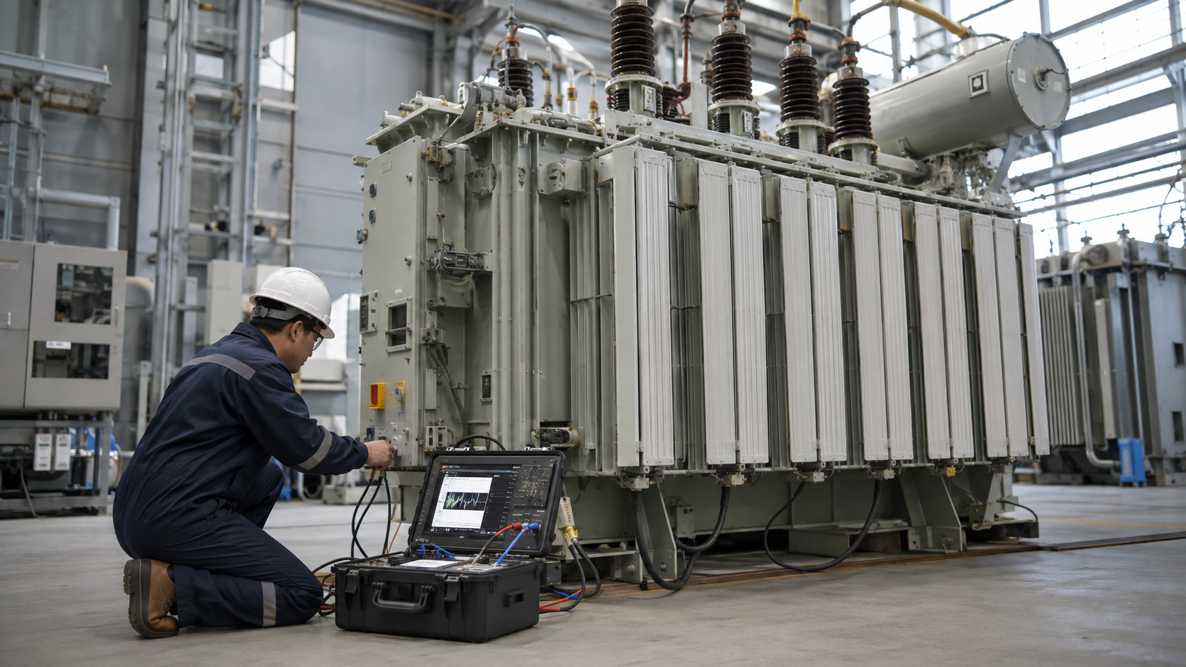
Commissioning should prove the complete protection chain, not only the CT winding. Begin with visual inspection: correct conductor routing, core closure, mounting, polarity, secondary terminal tightness and grounding arrangement. Check secondary continuity and insulation using methods approved for the connected equipment.
A primary-injection or equivalent functional test should create a known residual current through the CBCT. Confirm the relay displays the expected value, picks up at the specified setting, applies the intended time delay and operates the correct alarm or breaker trip output. Test the trip circuit to the interrupting device under controlled conditions. Record injected current, relay indication, pickup, trip time and final settings for the asset file.
Do not validate a CBCT by passing only one phase conductor through the core during normal service. That would make ordinary load current appear as a severe residual current. Testing must be performed by qualified personnel using an approved test connection. For wider context on instrument transformers and magnetic behavior, see our guide to transformer types and construction.
Common CBCT problems and troubleshooting clues
- Nuisance trips under normal load: check whether the neutral, cable screens or grounding conductors bypass the intended window arrangement; then review relay pickup and time delay.
- No trip during a test: verify the test current actually creates imbalance, confirm secondary continuity and polarity, and inspect the relay input and trip supply.
- Unstable readings: look for loose terminals, excessive secondary burden, nearby interference, a split core that is not fully closed, or contaminated mating surfaces.
- Trip only during energization: review transient response, cable charging current, downstream filters or drives, relay delay and CBCT saturation with the protection engineer.
- Unexpected residual current: measure actual leakage and confirm that multiple circuits have not been routed through one window.
A CBCT should not be bypassed merely to stop nuisance trips. The trip may be revealing genuine insulation deterioration. Use a structured investigation and, where relevant, follow the testing principles in our transformer testing guide.
Key takeaway
A core balance current transformer is a precise way to detect current leaving its intended circuit. Its sensitivity comes from putting every live conductor through one core and measuring only their imbalance. Correct conductor routing, matched relay characteristics, controlled secondary burden and end-to-end commissioning are essential. For a project-specific selection, share the system voltage, cable arrangement, minimum earth-fault current, relay model, window requirement and installation environment with the equipment supplier and protection engineer.
Reading residual current and zero-sequence notation correctly
Protection drawings do not always use the same symbol for the measured quantity. In symmetrical-component notation, zero-sequence current I0 is one third of the three-phase current sum; the residual quantity is 3I0. A relay display may label residual current differently. Confirm the relay manual and ratio convention before translating a pickup setting into primary amperes. Treating I0 and the complete residual sum as interchangeable can introduce a factor-of-three error.
Normal load imbalance is not automatically an earth fault. If all intended return conductors pass through the window, their instantaneous currents still sum to approximately zero. An omitted neutral, unintended return route or incorrect screen arrangement can create a residual signal without the insulation fault the engineer intended to detect. That is why conductor routing belongs in both design and commissioning.
Check the complete relay path, not only the sensor
A CBCT output must be compatible with the relay input and the expected signal level. Window size, conductor position, secondary burden, lead length and relay sensitivity affect selection. Commissioning should verify both detection and the complete alarm or trip path. A successful relay test alone does not establish that the conductors have been routed correctly through the installed core.
Technical references
Use the device manual and project specification for the actual input range, ratio, burden and wiring. These references explain the protection-relay context and the broader standards or safety framework; they do not replace the approved equipment drawing.
- ABB REF615 application manual: describes residual-current relay inputs and the use of an external core-balance CT in supported configurations.
- IEC 61869-2 standard scope: inductive current transformers used with measuring instruments and protective devices.
- U.S. regulation 29 CFR 1910.333: electrical safety work practices for de-energized equipment and permitted exceptions.
Related transformer guides and product context
Review the transformer fundamentals guide for the underlying principles. For adjacent questions, read How to Test a Transformer: Methods, Sequence and Interpretation and What Is an Autotransformer? Principle, Uses and Limits. For any distribution-equipment application, confirm the actual product scope and ratings against the approved project documents.
Video: the underlying transformer principle
NPTEL IIT Kharagpur illustrates the electrical principle discussed here. This background explanation complements the article; it does not demonstrate or authorize field work.

Frequently asked questions
What does a core balance current transformer measure?
It measures the residual sum of the currents in all live conductors through its window. Intended outgoing and return currents cancel; current returning by an external path produces a residual signal.
Should the neutral pass through a CBCT?
For a circuit with a neutral, that live return conductor normally passes through the same window as the phases. The protective-earth arrangement must follow the approved protection drawing.
Is residual current the same as I0?
In symmetrical-component notation, the three-phase residual sum is 3I0. Check the relay display and manual before converting settings into primary amperes.
Why can a CBCT trip without a genuine insulation fault?
An omitted return conductor, incorrect screen routing, relay mismatch or wiring problem can create an unwanted signal. Investigate the complete circuit before raising the pickup setting.
Can a CBCT replace all phase CTs?
No. A CBCT provides residual-current information; phase metering and many protection functions still need individual phase-current measurements.