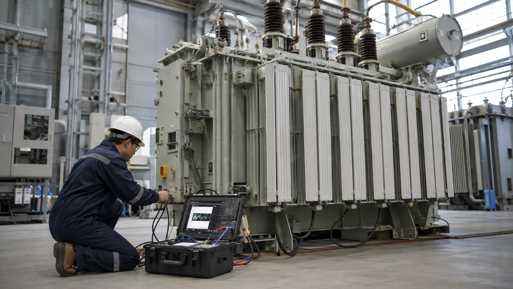
Fixing a transformer can take from a few hours to more than a year. A loose external connection, replaceable fuse or minor accessory fault may be corrected within 4–24 hours after safe isolation. A bushing, gasket, fan, pump or tap-changer accessory repair often takes 1–7 days if parts and qualified labor are available. Internal winding or core damage commonly requires workshop repair lasting several weeks or months. If the unit must be replaced, a stocked distribution transformer may restore service in hours or days, while a custom large power transformer can require a year or longer to manufacture and deliver.
| Repair situation | Typical working range | Main constraints |
|---|---|---|
| Inspection, reset or external connection | 4–24 hours | Safe access, fault confirmation, replacement hardware |
| Fuse, arrester, fan, gauge or control component | 1–3 days | Part availability and post-repair tests |
| Bushing, gasket, small oil leak or cable termination | 2–7 days | Oil handling, sealing, curing and electrical tests |
| On-load tap changer or cooler-system repair | Several days to 3 weeks | Damage, specialist crew and components |
| Internal inspection and winding repair | 4–16+ weeks | Transport, disassembly, drying, rewinding and factory tests |
| Custom large-transformer replacement | 12–36+ months in constrained markets | Engineering, manufacturing queue, materials and transport |
These are planning ranges, not promises. The clock that matters to the owner is total outage time, which includes isolation, diagnosis, approvals, repair, logistics, testing and re-energization. A ten-hour mechanical task can still create a week-long outage if the correct bushing is not in stock.
Why transformer repair time varies so much
“Transformer” covers pole-mounted distribution units, dry-type building transformers, industrial substation transformers and custom machines weighing hundreds of tons. The same symptom can also have very different causes. A protection trip might result from a downstream cable fault, a failed relay input or serious internal arcing. Repair work should not begin until the fault boundary is understood.
Five factors dominate the schedule:
- Damage severity: external accessories are accessible; winding deformation, core damage and contaminated insulation require major disassembly.
- Transformer size and construction: a small replaceable unit is easier to move and substitute than a custom high-voltage transformer.
- Parts and spares: a compatible item in local stock can shorten restoration dramatically. Custom bushings, tap-changer parts and windings create long lead times.
- Site and transport: permits, crane access, oil containment, road limits and factory distance can exceed the hands-on repair time.
- Testing and approval: the unit cannot safely return to service merely because a leaking seal or damaged component has been replaced.
The repair timeline, step by step
1. Make the area safe and stabilize the system
The first priority is people and the wider electrical system, not speed. Operators isolate the transformer, establish the required switching boundary, apply lockout/tagout, verify absence of voltage, ground where required and control fire or oil hazards. In the United States, OSHA 1910.333 generally requires exposed live parts to be de-energized before employees work on or near them, unless a stated exception applies. Utility work is also addressed by OSHA 1910.269.
This stage may take hours in a planned industrial outage or longer after a storm, fire or substation event. Backfeeds, parallel sources and stored energy must all be considered. Only qualified personnel should decide when the equipment is in an electrically safe work condition.
2. Diagnose the actual fault
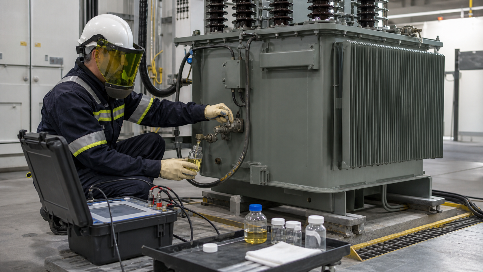
Technicians review relay targets, disturbance records, alarms, load history and recent maintenance. They inspect bushings, connections, cable boxes, radiators, gaskets, gauges, fans, pumps and the tap changer. Depending on the transformer, the test plan may include winding resistance, turns ratio, insulation resistance, power factor or dissipation factor, excitation current, sweep frequency response, oil quality and dissolved gas analysis.
A basic field assessment may take several hours. Laboratory oil results can take one or more days. Complex faults may require repeat samples, internal inspection or consultation with the original design records. Rushing this step can replace a visible failed part while leaving the initiating fault undiscovered.
3. Choose repair, refurbishment or replacement
The owner compares safety, technical risk, outage cost, remaining life and availability. A sound tank and active part may justify repair. Extensive winding damage, a badly distorted core, severe fire exposure or obsolete construction may favor replacement. Sometimes the fastest restoration uses a temporary mobile or spare transformer while the original unit receives a long workshop repair.
Do not confuse procurement lead time with physical installation time. A crew might remove and install a distribution transformer in one shift once an interchangeable spare is on site. The delay is often obtaining a unit with suitable kVA rating, voltage ratio, impedance, vector group, taps, insulation level, cooling, enclosure and connection arrangement.
4. Perform the repair
Minor field work includes tightening or replacing connections, repairing control wiring, replacing fans or pumps, correcting a small leak, fitting a bushing or servicing an accessible tap-changer mechanism. Oil work adds filtration, vacuum processing, leak checks and settling time. Weather and site cleanliness can limit when the tank may be opened.
Major repair usually moves the transformer to a qualified facility. The team drains oil, removes accessories, opens the tank, lifts the active part and documents the damage. Winding repair may require conductor fabrication, insulation work, coil pressing, core-and-coil reassembly, vapor-phase or oven drying, vacuum oil filling and a full test sequence. Each step has hold points; drying alone cannot be shortened arbitrarily without risking moisture in the insulation system.
5. Test, commission and return to service
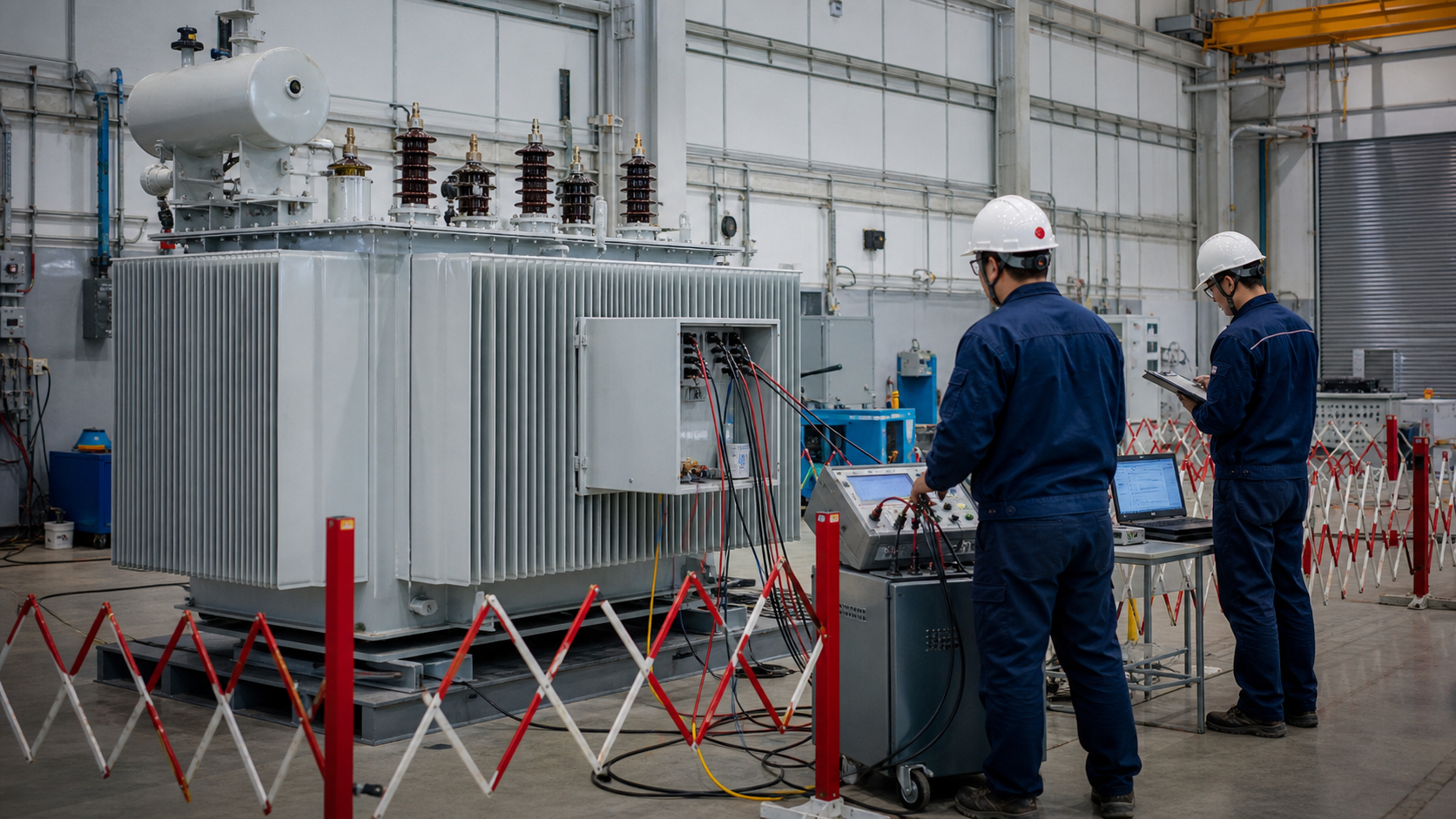
Post-repair testing should demonstrate that the fault is corrected and that the transformer is fit for its duty. The scope depends on what was disturbed. It may include ratio and polarity, winding resistance, insulation tests, oil tests, leak and pressure checks, cooling controls, alarms, protection, grounding and functional trip checks. Major workshop repairs may require an agreed set of factory acceptance tests.
At site, technicians reconnect primary, secondary and auxiliary systems, verify phasing and torque, inspect clearances, restore protection settings and complete commissioning records. Energization is a controlled operation followed by checks for abnormal sound, current, temperature, leakage and gas-relay indications.
Repair time by fault type
Blown fuse or external protective device
Replacement can be quick, but the cause must be found first. A fuse may have operated because of an internal transformer fault or a downstream short circuit. Simply installing another fuse without tests can expose personnel and equipment to a second failure.
Loose or overheated connection
If damage is limited to accessible hardware and the insulation system is unaffected, repair may fit within a planned shift. Burned terminals, carbon tracking or damaged bushings extend the scope. Thermography and torque records help identify adjacent weak points.
Oil leak
A small gasket leak may take one to several days once the replacement seal is available. The oil level, moisture ingress and cause of pressure must be assessed. Welding a tank, replacing a radiator or processing contaminated oil adds time and environmental controls.
Bushing failure
A stocked, compatible bushing may be changed in a few days, including oil management and electrical testing. A special high-voltage bushing can have a significant factory lead time. The investigation should also check whether contamination, connection heating, seismic stress or an internal fault caused the failure.
Tap changer problem
External drive or control faults may be corrected in days. Contact damage, diverter-switch work or contamination inside an on-load tap changer can take one to three weeks and requires a specialist familiar with that design.
Winding or core damage
Expect weeks or months. The transformer may require transport, teardown, engineering review, rewind, drying, reassembly and testing. If core steel, clamping structures or the tank are seriously damaged, replacement may be more practical than repair.
Repair versus replacement: what changes the answer?
For smaller standard units, replacement is often the fastest restoration method. For large custom units, repairing the existing transformer may be quicker than waiting for a new one. The U.S. Department of Energy notes that large power transformers are custom-made, difficult to transport and can have lead times of a year or more in its Transformer Resilience and Advanced Components program.
New-equipment procurement is separate from field repair. Obtain a current quotation for the exact design; historical supply-chain figures cannot establish the restoration time for this incident.
A sound decision uses more than age. Review diagnostic condition, failure mechanism, design support, loss performance, future load, safety upgrades, repair warranty and the cost of another outage. See our complete transformer installation and maintenance guide for lifecycle planning.
How to shorten transformer downtime safely
- Maintain complete records: nameplate data, drawings, oil history, test baselines, relay files and previous repairs reduce diagnostic delay.
- Define critical spares: stock common fans, pumps, gauges, gaskets, relays and site-specific bushings where the risk justifies it.
- Prequalify service providers: establish contacts, lifting capability, oil handling and emergency terms before a failure.
- Plan temporary supply: identify switching alternatives, rental transformers, mobile substations and compatible spare units.
- Use condition-based maintenance: trending can reveal deterioration while a planned outage is still possible. The installation and maintenance pillar guide covers practical inspection and lifecycle planning.
- Prepare transport studies: large units may need route surveys, permits, cranes, foundations and oil-containment arrangements.
The safest fast repair is prepared in advance. Skipping isolation, diagnosis, drying or acceptance tests may shorten the visible job but increases the chance of rework, repeat failure and injury.
What information should you give a repair company?
Provide nameplate photographs, transformer type, kVA or MVA, primary and secondary voltages, vector group, impedance, tap range, cooling class, oil type, installation location and the exact time and operating condition when the event occurred. Add relay targets, event records, alarms, photographs, oil observations, sounds, odors and any tests already completed.
Ask the service provider to separate the schedule into diagnosis, engineering, parts, field work or factory work, transport, testing and contingency. The quotation should state assumptions and the criteria for declaring the transformer repairable. Use the methods in our transformer testing guide to understand common diagnostic evidence, review the transformer primary protection guide before returning the unit to service, and compare suitable replacement options in the LBAJI transformer range.
Repair time, outage time and procurement lead time
These are three different clocks. Repair time is the work required to restore the damaged asset. Customer outage time can end earlier if a compatible spare or an alternate feeder supplies the load. Procurement lead time describes obtaining a new unit and may continue long after the site has temporary power. Ask the utility or contractor which clock its estimate refers to before communicating a restoration commitment.
For example, a crew may isolate a failed distribution unit, install a stocked replacement and restore customers while the original transformer awaits workshop assessment. Conversely, a modest accessory repair can cause a long outage if the site cannot be safely accessed or switched. The practical question is therefore “what is the earliest safe supply-restoration route?” as well as “how long does the damaged transformer take to repair?”
Any hours-or-days range in this guide is a planning illustration, not a service guarantee or industry-wide measured average. Actual timing must come from the owner or service provider after confirming the fault, spare compatibility, access and acceptance tests. Historical factory lead-time figures should not be presented as a current quotation or used to predict a particular local outage.
Related transformer guides and product context
Review the transformer fundamentals guide for the underlying principles. For adjacent questions, read What Happens When a Transformer Blows? Causes and Response and How to Test a Transformer: Methods, Sequence and Interpretation. For distribution-equipment specifications, see the 35 kV oil-immersed power transformer; confirm the actual product scope and ratings before using it in a project.
Video: the underlying transformer principle
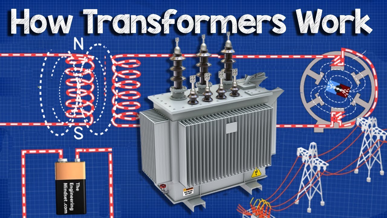
The Engineering Mindset illustrates the electrical principle discussed here. This background explanation complements the article; it does not demonstrate or authorize field work.
Frequently asked questions
Can a transformer be fixed in one day?
An accessible external fault may be corrected within a day when compatible parts and qualified crews are available. Internal damage, access restrictions and acceptance tests can extend the job.
Is replacement always slower than repair?
No. A compatible stocked spare can restore supply while the original unit undergoes workshop repair. A custom replacement without a spare can take much longer to obtain.
Does a restored supply mean the damaged transformer is repaired?
No. Supply may have been transferred to an alternate feeder or a replacement unit. Ask whether an estimate describes customer restoration, equipment repair or procurement.
What usually delays transformer repair?
Uncertain fault location, unavailable accessories, transport, specialist labor, oil handling, drying and tests can each control the critical path. The actual cause determines which matters most.
Who can give a reliable restoration estimate?
The responsible utility or service provider after assessing isolation, damage, access, spare compatibility and testing. General planning ranges are not a promise for a specific outage.