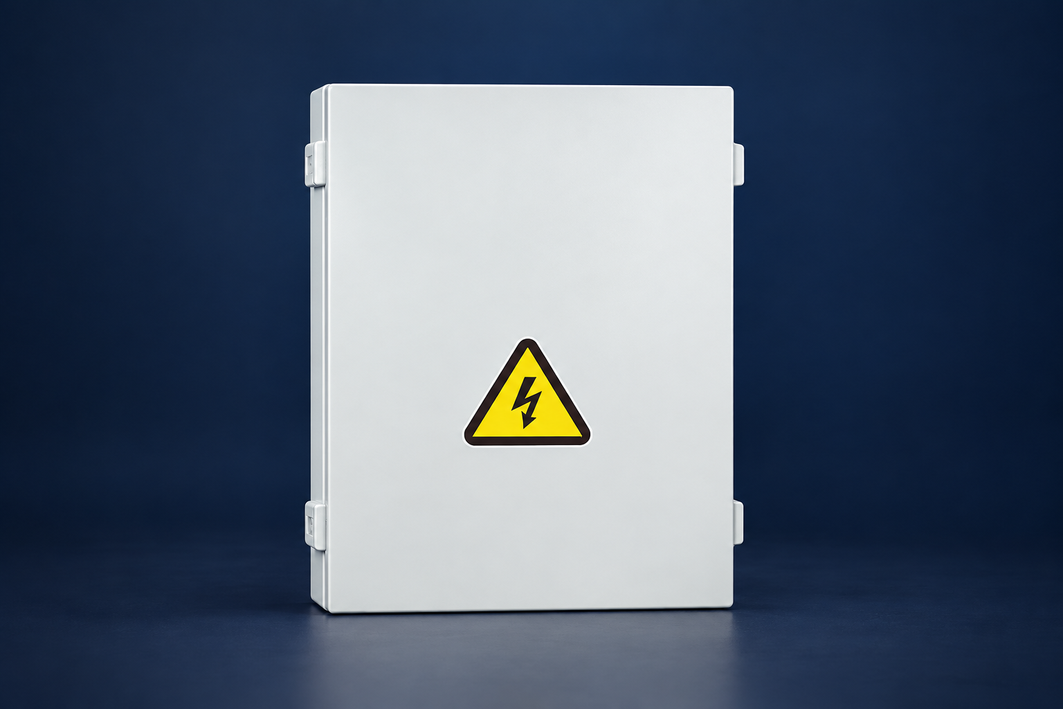
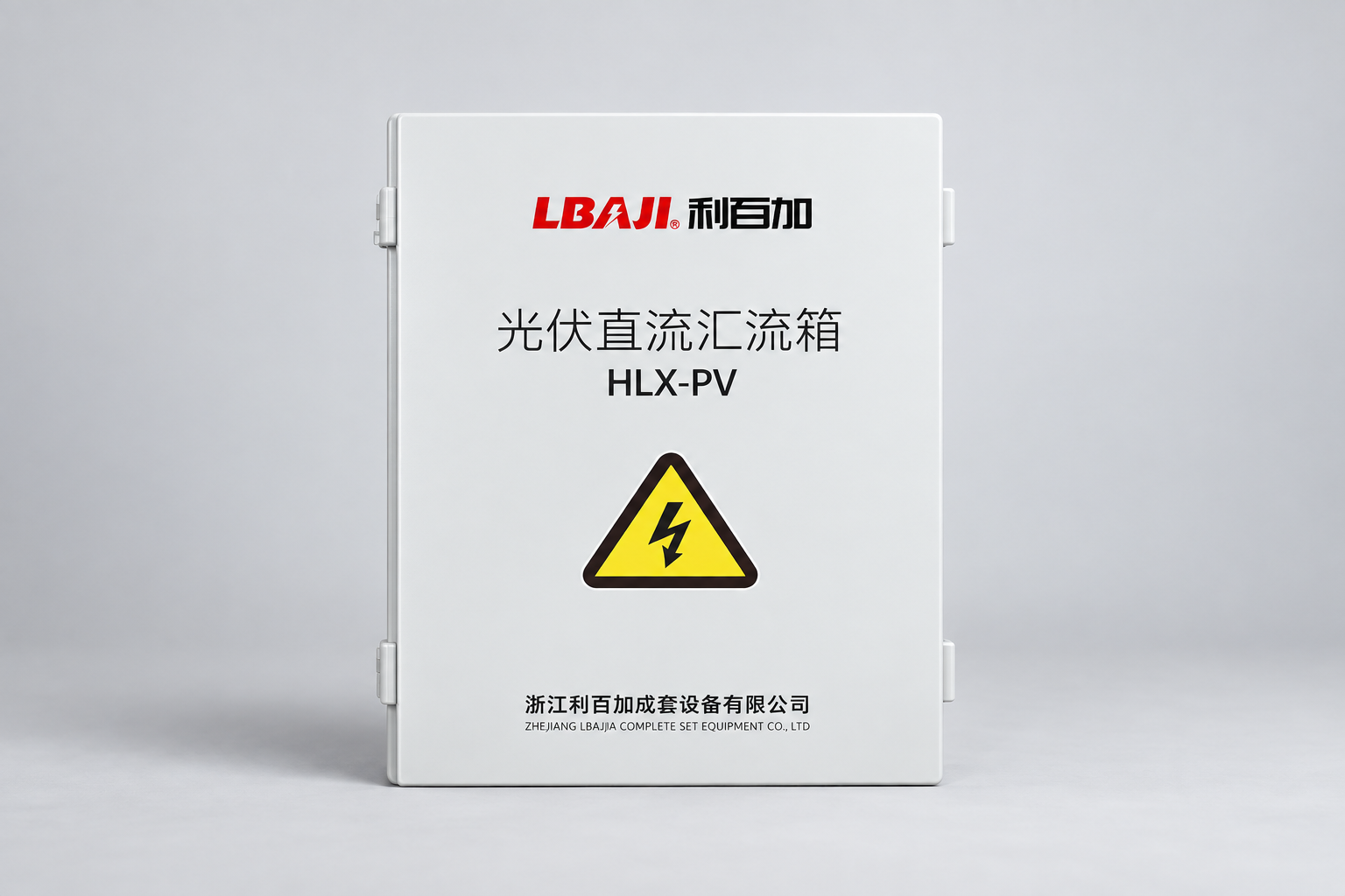
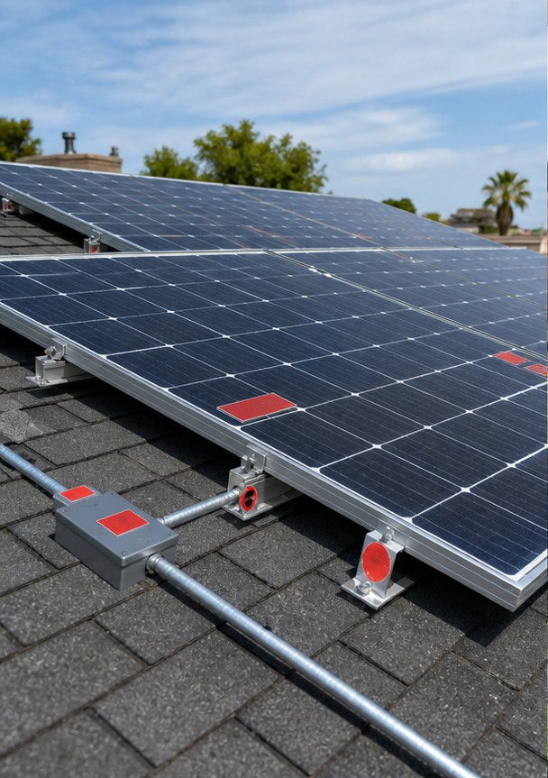
A solar panel combiner box brings multiple photovoltaic (PV) string circuits together before an inverter or DC distribution point. Depending on the design, it also provides string overcurrent protection, a DC-rated disconnect, surge protection and monitoring. Select it from the number of strings, the cold-weather maximum open-circuit voltage, corrected short-circuit current, inverter input limits and installation environment—not the panel wattage alone. A separate box is not always necessary when an inverter already provides the required combining and protection. The final arrangement must be checked against the adopted electrical code and the equipment instructions.
Key Selection Points
- Count the strings feeding each inverter input or MPPT; do not join unrelated MPPT groups on one output.
- Check the maximum cold-weather string voltage against every DC component rating.
- Document string protection, output current, enclosure conditions and the approved one-line diagram before ordering.
Where the Combiner Box Sits

Each series-connected module string arrives at the combiner on positive and negative conductors. Fuses or breakers protect individual strings where required, busbars combine them, and one larger pair leaves for the inverter or DC disconnect. Systems with one or two strings may not require a separate combiner; the inverter may already include the function.
Solar Combiner Box Selection Checklist
The first design question is whether strings are meant to combine at all. The array layout, inverter input and protective-device requirements control that choice. IEC 62548-1 addresses PV array wiring, electrical protection, switching and earthing. Use the edition adopted for the project, plus local rules and manufacturer instructions, before fixing component ratings.
| Decision | Information to collect | What the selected box must match |
|---|---|---|
| Input circuits | Strings per inverter input or MPPT, polarity and spare capacity | Protected input positions and the intended one-line arrangement |
| DC voltage | Module Voc, modules per string and lowest expected cell temperature | Maximum rating of the enclosure assembly, fuses, holders, switch and SPD |
| Current | Module Isc, parallel strings and adopted-code correction factors | String devices, output bus, terminals and conductor ratings |
| Protection | Module maximum series fuse rating and reverse-current exposure | PV-rated fuses or breakers and documented interruption duty |
| Installation | Indoor/outdoor location, heat, UV, water, corrosion and access | Enclosure rating, cable entries, thermal design and maintenance clearance |
| Monitoring | Fault detection and reporting requirements | Current sensors, alarm interfaces and power supply where specified |
Core Components
A typical box includes touch-safe string fuse holders or DC breakers, positive and negative busbars, a DC isolator, Type 2 surge protective devices where the risk assessment calls for them, grounding terminals, glands and a weather-resistant enclosure. Monitoring versions add current sensors and communications. All devices must carry a genuine DC voltage and interruption rating.
Verify every fuse, switch and surge protective device is rated for the applicable DC voltage, current and interruption duty; confirm the offered part numbers on the approved schedule.
Voltage and Current Sizing
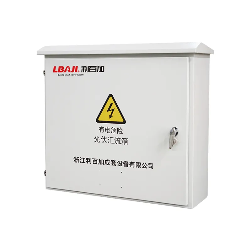
Correct the module open-circuit voltage for the lowest expected cell temperature and keep the resulting string voltage below every component’s maximum. Correct short-circuit current using the factors required by the applicable standard, then size string protection, combined output conductors and isolators. Verify that the inverter MPPT voltage and input-current limits are not exceeded.
Fuse Selection and Reverse Current
String fuses protect a faulted string from reverse current supplied by parallel strings. Use the module’s maximum series fuse rating, calculated string current and the number of parallel sources. A fuse that is merely equal to operating current may nuisance-open; one above the module limit may fail to protect the conductors and modules.
Keep the module maximum-series-fuse rating, corrected string current, expected reverse current and selected device rating together on the calculation record. Use the adopted code edition and module/inverter instructions for any required factors.
SPD, Grounding and Polarity
Select surge protection for the PV earthing arrangement and maximum continuous operating voltage. Keep SPD leads short and direct. Maintain polarity throughout installation, bond exposed metal as required and do not assume the negative conductor is grounded. Incorrect polarity can damage an inverter even if the box appears otherwise correct.
Outdoor Enclosure and RFQ Checklist
Specify string count, module Voc and Isc, temperature range, system maximum voltage, inverter data, output cable, grounding method, required monitoring, enclosure rating, corrosion exposure and standard. Locate the box to reduce cable length while preserving shade, drainage, working clearance and safe access.
Choose the Input Count and Keep MPPT Groups Separate
Count the physical strings that actually arrive at the box, not the number of modules. A four-string array needs four input positions if each string is landed separately. If the inverter has two independent maximum-power-point trackers, document which strings belong to each tracker. Do not combine unlike orientations or array groups into one bus and then split the output across independent inverter inputs without an approved design. String mismatch can reduce performance, and an incorrect connection can exceed input or protection limits.
Allow for planned expansion only where the output bus, conductors, protection and inverter input can also handle it. An empty terminal does not create spare electrical capacity. The input-count decision should appear on a one-line diagram with each string ID, module count, fuse position and output destination. That drawing is also useful for commissioning and later fault isolation.
Check Cold-Weather Voltage and Combined Current
Series module voltages add. Start with module open-circuit voltage and its temperature coefficient, then calculate the maximum string voltage at the lowest expected cell temperature. Compare that result with the DC voltage rating of every component in the current path, including fuse holders, disconnects, surge protective devices, busbars, terminals and the inverter input. A nominal operating voltage or room-temperature Voc is not enough. Do not rely on a catalogue headline if a component inside the assembly has a lower rating.
Parallel string currents add. The output path must carry the maximum corrected current of the strings assigned to it. For an illustrative arithmetic check, four identical strings at 12 A short-circuit current sum to 48 A before any adjustment required by the adopted code or module technology. That does not make a 48 A switch or conductor automatically suitable; the designer must apply the relevant factors, terminal temperature limits and continuous-duty rules. The University of Maryland Extension’s solar wiring and fusing guide explains why PV conductor and overcurrent choices follow the full circuit design.
Specify DC Protection, Disconnects and Surge Devices
String fuses or breakers are selected for the array’s possible reverse current, module maximum series fuse rating, calculated circuit current and available fault duty. They need a genuine DC rating at the system voltage. An AC-only breaker with a similar ampere number is not interchangeable with a PV DC device. UL Solutions lists separate applicable standards for PV fuses, disconnects, breakers, holders and combiner boxes; a project should request evidence for the complete offered assembly and its components rather than assume certification from a generic description.
A disconnect is intended to isolate a circuit under its rated conditions. A surge protective device has another function: limiting transient overvoltage. Neither replaces the other. Select SPD type, continuous operating voltage and coordination for the earthing arrangement and exposure. IEC 61643-32 covers PV SPD selection, installation and coordination. Keep the protective-earth path and SPD leads consistent with the approved design; poor routing can compromise protection.
Plan the Outdoor Enclosure and Maintenance Access
Combiner boxes often sit near an array, where solar heating, rain, ultraviolet exposure and cable movement matter. Specify the required enclosure protection level for the actual site, but also review heat rise inside the enclosure, gland sealing, drainage, corrosion, snow or dust exposure and safe working access. An IP label alone does not establish thermal performance or prove that an assembly suits a coastal or rooftop installation. Ask for the assembly drawing, enclosure material, cable-entry layout and environmental test evidence.
Place the box where string cables can be routed without excessive runs while preserving clear access for isolation, inspection and maintenance. Keep labels and circuit IDs readable. Confirm that technicians can identify each input and isolate the intended circuit without disturbing adjacent live circuits. PV strings may remain energized in daylight, so inspection and installation should follow qualified-person procedures and the equipment instructions.
Compare the Relevant LBAJI Equipment
The LHLX-PV24/Z/D photovoltaic DC bus box is the relevant product family for string-side DC combining. Its public listing describes multiple input-count variants, but contains differing voltage statements across its text and table. Treat no voltage value from that page as a confirmed quotation. Request a current signed datasheet stating the exact input count, maximum DC voltage, per-input and total current, devices, enclosure and test basis for the proposed configuration.
The separate LHLX-AC photovoltaic bus box combines AC outputs after string inverters. It is not a substitute for DC string protection. For system context, use the PV combiner-box overview, the PV warning-label guide and the PV connector guide. Send the one-line diagram and module/inverter data with an inquiry so the offered assembly can be checked against the actual system.
Frequently Asked Questions
Does every solar array need a combiner box?
No. Small arrays or inverters with integrated combining and protection may not need a separate box.
Can AC breakers be used for PV strings?
Only devices specifically rated and listed for the DC voltage, current, polarity and interruption duty should be used.
How many strings can one combiner accept?
It depends on the number of protected inputs, bus rating and inverter input limits.
What causes a combiner box to overheat?
Loose terminals, undersized conductors, poor fuse contact, excessive current, solar heating and inadequate enclosure thermal design are common causes.
Is an SPD mandatory?
Requirements depend on the standard, lightning exposure, system layout and risk assessment, but it is often prudent or required.
Worked Procurement Example
Suppose a project has eight PV strings, grouped into two sets of four feeding two independent inverter MPPT inputs. The initial request is not simply “one eight-input box.” It should state whether the arrangement needs two independent four-input outputs in one assembly, two smaller boxes, or a manufacturer-approved alternative. Show the module count and orientation for each string, its cold-weather maximum voltage, Isc, maximum series fuse rating and the inverter’s input limits. Then state the site environment, monitoring need and required isolating arrangement.
Ask the supplier to mark the proposed one-line diagram with input and output terminal IDs, fuse or breaker ratings, DC disconnect rating, SPD data, enclosure details and all electrical ratings. Check that the quoted output is intended for the correct MPPT and that no return path, earthing connection or polarity is left implicit. This example contains no universal voltage or fuse size because those values come from the selected modules, inverter and adopted electrical rules.
Commissioning and Service Checks
Before energizing, compare labels and the as-built wiring with the approved one-line diagram. A qualified installer should verify polarity, continuity and insulation using procedures appropriate to the equipment and local code. Confirm the torque records for terminals where required, the fitted fuse or breaker type, SPD status, enclosure seals and the operation of the disconnect. Record string-current readings under comparable conditions so a later low-output investigation has a useful baseline. Do not use a current reading taken under different irradiance as proof that one string is defective.
Acceptance Records to Keep
Retain the approved data sheet, drawings, deviation list, material certificates where applicable, routine and special test reports, protection settings, commissioning results, photographs and final nameplate details. Record test conditions as well as values, because temperature, instrument method and connection can affect comparison. These documents establish the baseline used to investigate later alarms, loading changes or deterioration. They also prevent replacement equipment from being ordered from an incomplete description after personnel or suppliers change.
Solar PV System Video
NREL’s Solar 101 lecture, listed by the U.S. Department of Energy’s Building America Solution Center, explains the wider PV system in which a combiner may be used. It is background education, not wiring or certification instructions for a particular box.
Watch the NREL Solar 101 lecture on YouTube.
Conclusion
A solar panel combiner box joins several PV string outputs into one feeder while providing string overcurrent protection, DC isolation and optional surge protection and monitoring. It is sized from maximum PV voltage, corrected short-circuit current, string count, conductor ratings and the inverter input—not panel watts alone. Use project data and documented acceptance criteria before purchase, installation or service.