Overview
Resin insulated dry-type transformers are our company’s introduction of advanced foreign technology and independent development of SC9, SCB9 series, as well as SC10, SCB10 series with filler thin insulated dry-type transformers. Due to the damaged coil being encapsulated with oxygen resin, they are flame retardant, fireproof, explosion-proof, maintenance free, pollution-free, small in size, and can be directly installed in load centers. At the same time, the scientific and reasonable design and pouring process result in smaller partial discharge, low noise, and strong heat dissipation capacity of the product. It can operate for a long time under 140% rated load under forced air cooling conditions, and is equipped with an intelligent temperature controller with fault alarm,overtemperature alarm, overtemperature trip, and black gate functions. It is connected to the computer through RS485 serial interface for centralized monitoring and control.
Due to the above characteristics of our dry-type transformers, they are widely used in power transmission and transformation systems.such as hotels, restaurants, airports, high-rise buildings, commercial centers, residential areas and other important places, as well as in harsh environments such as subways, smelting power plants, ships, and offshore drilling platforms.
High voltage winding
The high-voltage winding is vacuum cast with epoxy resin with fillers, greatly reducing the local discharge and improving the electrical strength of the coil. The inner and outer walls of the winding are filled with glass fiber mesh plates, enhancing the mechanical strength of the coil and improving the product’s ability to resist sudden short circuits. The coil never cracks.
Manufacturing process
The coil is wound on a high-precision winding machine, and the low-votage winding adopts a foil winding structure. when the transformer capacity is large, there is a ventilation duct. After the winding is completed, vacuum drying is carried out, and the entire pouring and curing process is completely operated according to the process requirements. All processes need to be strictly monitored and adjusted according to the situation. The precision manufacturing process of pouring ensures that the coil has no bubbles or voids,resulting in high-quality operation of the transformer.
Temperature control system and air cooling system
The cross flow top blowing cooling fan is adopted, which has the characteristics of low noise, high air pressure, and beautiful appearance, enhancing the overload capacity of the transformer. The temperature control adopts an intelligent temperature controller.which improves the safety and reliability of transformer operation.
Protect the casing and output busbar
The protective shell provides further safety protection for the transformer, with protection levels of IP20, IP23, etc. The shell material includes cold-rolled steel plate, stainless steel plate, etc, for users to choose from. Low voltage outgoing lines use standard bus bars,both side and top outgoing lines can be used, and special outgoing methods can also be designed for users.
Transformer outgoing line method
Conventional outgoing lines, standard enclosed busbars, and standard side outgoing lines can be manufactured according to different interface forms, and special outgoing methods can also be designed according to user requirements.
![]()
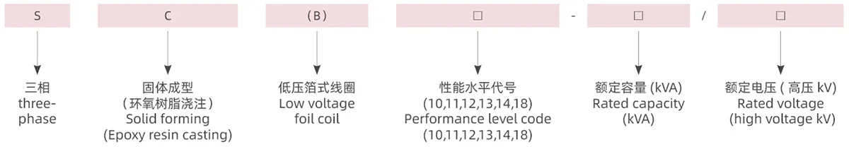
Model Meaning
Related standards¶meters
- GBT10228-2015,GB1094.11-2007,GB20052-2020,JBT10088-2004,GB4208-1993
- Rated high voltage: 10 (11,10.5,6.6,6.3,6) KV
- Rated low voltage: 0.4KV
- Connection group: Dyn11 or Yyn0
- High voltage tap range: ±5 or ±2×2.5%
- Insulation level: LI75AC35/LI0AC5
- Frequency: 50Hz
Appearance and installation dimensions
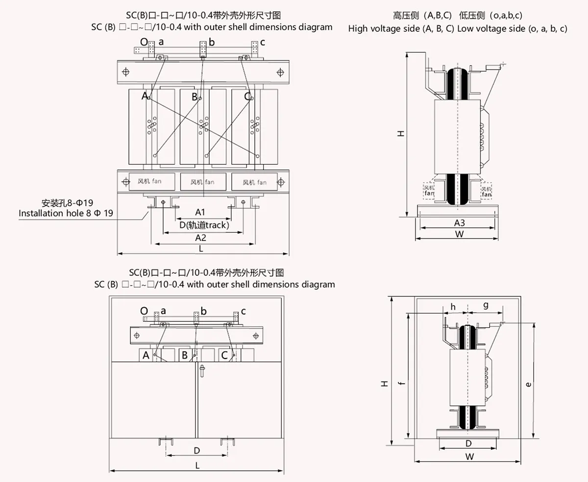
Appearance and installation dimensions
10KV SC(B)11RESIN INSULATION DRY TRANSFORMER SERIES
![]()
10KV SC(B)13RESIN INSULATION DRY TRANSFORMER SERIES
![]()
Note: The dimensions and weight provided are only for reference in the design and selection, and the final dimensions and weight are subject to our company’s product drawings.
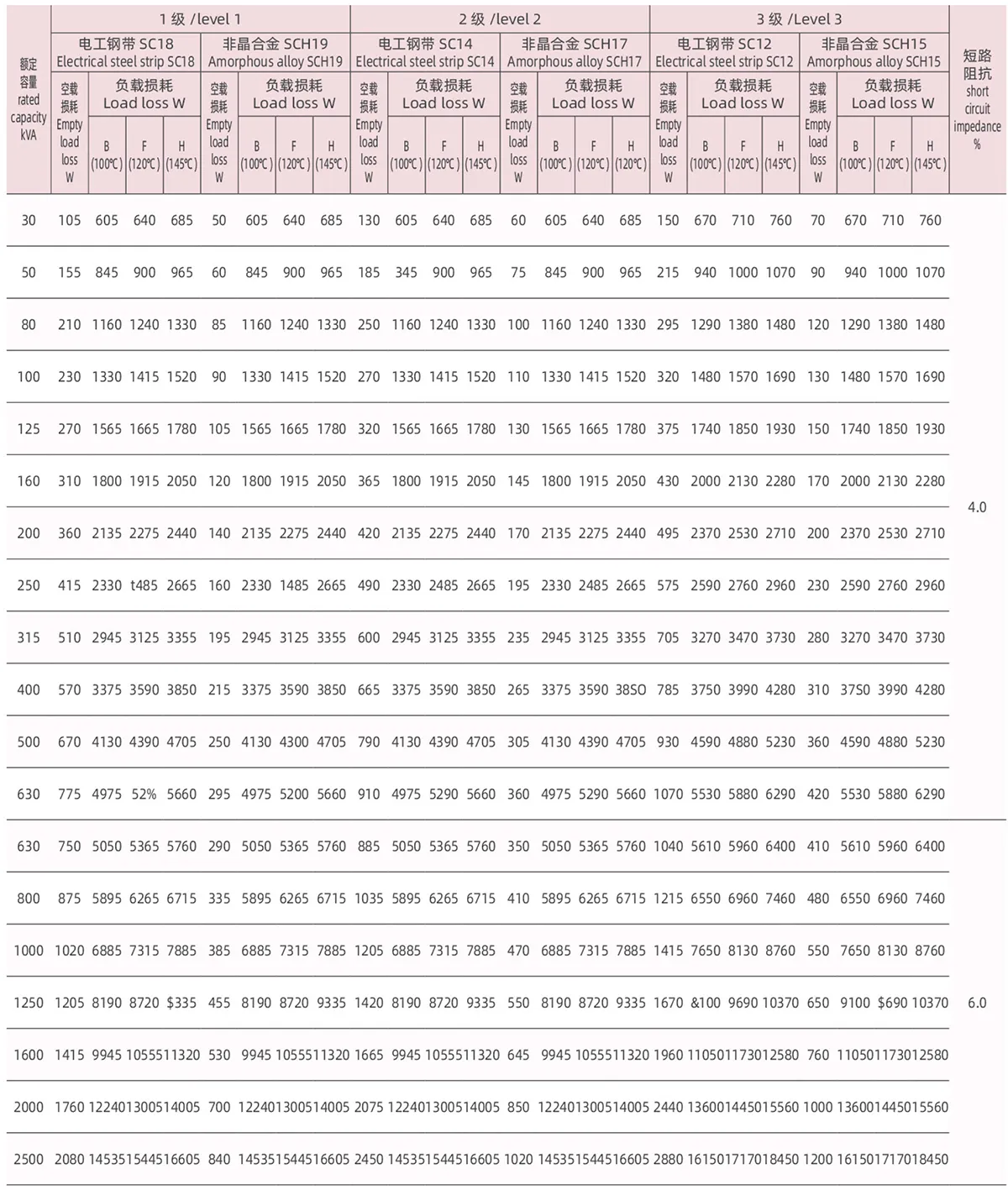
Technical parameters
10KV SC(B)11 series resin insulated dry-type transformers
6kV, 10kV class 30kV∙A~2500kV∙A non-excitation voltage regulating distribution transformer
| Rated capacity (KVA) |
Voltage combination and tap range (kV) |
connection symbol |
No load loss (kW) |
Load loss at different insulation system temperatures (Kw) |
No load current (%) |
Short circuit impedance (%) |
Weight (kg) |
Dimensions(mm) (L in length,B in width,and H in height) |
Installation size |
With shell size (L×W×H) |
||||
| High Pressure (kV) |
High voltage division Range of acceptance (%) |
Low Pressure (kV) |
130℃(B) (100℃) |
155℃(B) (120℃) |
80℃(B) (145℃) |
|||||||||
| 30 | 6 6.3 6.6 10 10.5 11 |
±2.5 ±5 |
0.4 | Dyn11 Yyn0 |
0.17 | 0.67 | 0.71 | 0.76 | 2 | 4 | 270 | 590×500×640 | 400/400 | 1000×900×2200 |
| 50 | 0.24 | 0.94 | 1 | 1.07 | 2 | 360 | 620×550×670 | 400/400 | 1000×900×2200 | |||||
| 80 | 0.33 | 1.29 | 1.38 | 1.48 | 1.5 | 510 | 680×580×710 | 400/450 | 1050×950×2200 | |||||
| 100 | 0.36 | 1.48 | 1.57 | 1.69 | 1.5 | 570 | 720×600×720 | 400/450 | 1100×950×2200 | |||||
| 125 | 0.42 | 1.74 | 1.85 | 1.98 | 1.3 | 600 | 860×650×850 | 550/550 | 1250×1000×2200 | |||||
| 160 | ±2×2.5 ±5 |
0.48 | 2 | 2.13 | 2.28 | 1.3 | 730 | 900×710×890 | 550/550 | 1300×1050×2200 | ||||
| 200 | 0.56 | 2.37 | 2.53 | 2.71 | 1.1 | 850 | 940×750×980 | 550/660 | 1300×1100×2200 | |||||
| 250 | 0.65 | 2.59 | 2.76 | 296 | 1.1 | 960 | 960×770×1030 | 660/660 | 1300×1100×2200 | |||||
| 315 | 0.79 | 3.27 | 3.47 | 3.73 | 1 | 1130 | 1020×790×1060 | 660/660 | 1400×1150×2200 | |||||
| 400 | 0.88 | 3.75 | 3.99 | 4.28 | 1 | 1330 | 1060×880×1100 | 660/820 | 1450×1200×2200 | |||||
| 500 | 1.04 | 4.59 | 4.88 | 5.23 | 1 | 1480 | 1080×900×1160 | 660/820 | 1450×1200×2200 | |||||
| 630 | 1.17 | 5.61 | 5.96 | 6.4 | 0.85 | 6 | 1580 | 1200×920×1150 | 820/820 | 1550×1200×2200 | ||||
| 800 | 1.37 | 6.55 | 6.96 | 7.46 | 0.85 | 1910 | 1260×920×1260 | 820/820 | 1600×1200×2200 | |||||
| 1000 | 1.59 | 7.65 | 8.13 | 8.76 | 0.85 | 2260 | 1320×940×1300 | 820/820 | 1700×1250×2200 | |||||
| 1250 | 1.88 | 9.1 | 9.69 | 10.3 | 0.85 | 2660 | 1380×950×1380 | 820/820 | 1750×1250×2200 | |||||
| 1600 | 2.2 | 11 | 11.7 | 12.5 | 0.85 | 3180 | 1460×1120×1490 | 1070/1070 | 1850×1400×2200 | |||||
| 2000 | 2.75 | 13.6 | 14.4 | 15.5 | 0.7 | 3600 | 1490×1120×1620 | 1070/1070 | 1900×1450×2200 | |||||
| 2500 | 3.24 | 16.1 | 171 | 18.4 | 0.7 | 4220 | 1520×1120×1760 | 1070/1070 | 1950×1500×2200 | |||||
| 3150 | 4.62 | / | 22.5 | / | 0.6 | 5000 | 1600×1120×1860 | 1070/1070 | 2000×1550×2200 | |||||
| 4000 | 5.36 | 1 | 27 | / | 0.6 | 6300 | 1600×1120×1861 | 1070/1070 | 2100×1600×2200 | |||||
10KV SC (B) 13 series resin insulated dry-type transformer
6kV, 10kV class 30kV∙A~2500kV∙A non-excitation voltage regulating distribution transformer
| Rated capacity (KVA) |
Voltage combination and tap range (kV) |
connection symbol |
No load loss (kW) |
Load loss at different insulation system temperatures (Kw) |
No load current (%) |
Short circuit impedance (%) |
Weight (kg) |
Dimensions(mm) (L in length,B in width,and H in height) |
Installation size |
With shell size (L×W×H) |
||
| High Pressure (kV) |
High voltage division Range of acceptance (%) |
Low Pressure (kV) |
155℃(B) (120℃) |
|||||||||
| 30 | 6 6.3 6.6 10 10.5 11 |
±2.5 ±5 |
0.4 | Dyn11 Yyn0 |
0.14 | 0.71 | 2 | 4 | 270 | 590×500×640 | 400/400 | 1000×900×2200 |
| 50 | 0.19 | 1 | 2 | 360 | 620×550×670 | 400/400 | 1000×900×2200 | |||||
| 80 | 26 | 1.38 | 1.5 | 510 | 680×580×710 | 400/450 | 1050×950×2200 | |||||
| 100 | 29 | 1.57 | 1.5 | 570 | 720×600×720 | 400/450 | 1100×950×2200 | |||||
| 125 | 34 | 1.85 | 1.3 | 600 | 860×650×850 | 550/550 | 1250×1000×2200 | |||||
| 160 | ±2×2.5 ±5 |
0.38 | 2.13 | 1.3 | 730 | 900×710×890 | 550/550 | 1300×1050×2200 | ||||
| 200 | 0.45 | 2.53 | 1.1 | 850 | 940×750×980 | 550/660 | 1300×1100×2200 | |||||
| 250 | 0.52 | 2.76 | 1.1 | 960 | 960×770×1030 | 660/660 | 1300×1100×2200 | |||||
| 315 | 0.63 | 3.47 | 1 | 1130 | 1020×790×1060 | 660/660 | 1400×1150×2200 | |||||
| 400 | 7 | 3.99 | 1 | 1330 | 1060×880×1100 | 660/820 | 1450×1200×2200 | |||||
| 500 | 83 | 4.88 | 1 | 1480 | 1080×900×1160 | 660/820 | 1450×1200×2200 | |||||
| 630 | 94 | 5.96 | 0.85 | 6 | 1580 | 1200×920×1150 | 820/820 | 1550×1200×2200 | ||||
| 800 | 1.1 | 6.96 | 0.85 | 1910 | 1260×920×1260 | 820/820 | 1600×1200×2200 | |||||
| 1000 | 1.27 | 8.13 | 0.85 | 2260 | 1320×940×1300 | 820/820 | 1700×1250×2200 | |||||
| 1250 | 15 | 9.69 | 0.85 | 2660 | 1380×950×1380 | 820/820 | 1750×1250×2200 | |||||
| 1600 | 176 | 117 | 0.85 | 3180 | 1460×1120×1490 | 1070/1070 | 1850×1400×2200 | |||||
| 2000 | 2.2 | 14.4 | 0.7 | 3600 | 1490×1120×1620 | 1070/1070 | 1900×1450×2200 | |||||
| 2500 | 26 | 171 | 0.7 | 4220 | 1520×1120×1760 | 1070/1070 | 1950×1500×2200 | |||||
| 3150 | 3.7 | 22.5 | 0.6 | 5000 | 1600×1120×1860 | 1070/1070 | 2000×1550×2200 | |||||
| 4000 | 43 | 27 | 0.6 | 6300 | 1600×1120×1861 | 1070/1070 | 2100×1600×2200 | |||||
35KV SC (B) 10 series resin insulated dry-type transformer
35kV level 50kV∙A~2500kV∙A non excited voltage regulating distribution transformer
| Rated capacity (KVA) |
Voltage combination and tap range (kV) |
Coupling Group Number |
Empty load loss (kW) |
Temperature of different insulation systems Load loss below(KW) |
Empty load current (%) |
Short circuit impedance (%) |
Weight (kg) |
Dimensions(mm) (L in length,B in width,and H in height) |
Installation size |
With shell size (L×W×H) |
||
| High Pressure (kV) |
High voltage division Range of acceptance (%) |
Low Pressure (kV) |
155℃(B) (120℃) |
|||||||||
| 50 | 35 36 37 38.5 |
±2.5 ±5 |
0.4 | Dyn11 Yyn0 |
0.45 | 1.42 | 2.3 | 6 | 600 | 1000×870×1150 | 550/550 | 1700×1400×2200 |
| 100 | 0.63 | 2.09 | 2 | 900 | 1080×870×1330 | 550/550 | 1800×1400×1550 | |||||
| 160 | 0.79 | 2.81 | 1.5 | 1180 | 1480×870×1360 | 320/820 | 2200×1500×2200 | |||||
| 200 | ±2×2.5 ±5 |
0.88 | 3.32 | 1.5 | 1360 | 1500×870×1400 | 820/820 | 2250×1500×2200 | ||||
| 250 | 0.99 | 3.8 | 1.3 | 1560 | 1530×870×1430 | 820/820 | 2300×1500×2200 | |||||
| 315 | 1.17 | 4.51 | 1.3 | 1750 | 1560×870×1520 | 820/820 | 2300×1600×2200 | |||||
| 400 | 1.37 | 5.41 | 1.1 | 2150 | 1700×870×1680 | 820/820 | 2450×1600×2200 | |||||
| 500 | 1.62 | 6.65 | 1.1 | 2450 | 1740×870×1860 | 820/820 | 2450×1600×2200 | |||||
| 630 | 1.86 | 7.69 | 1 | 2840 | 1840×1120×1960 | 1070/1070 | 2550×1700×2200 | |||||
| 800 | 2.16 | 9.12 | 1 | 3420 | 1860×1120×2150 | 1070/1070 | 2550×1700×2200 | |||||
| 1000 | 2.43 | 10.4 | 0.75 | 4130 | 1900×1120×2220 | 1070/1070 | 2600×1800×2200 | |||||
| 1250 | 2.83 | 12.7 | 0.75 | 4820 | 1940×1120×2260 | 1070/1070 | 2650×1800×2200 | |||||
| 1600 | 3.24 | 15.4 | 0.75 | 5700 | 1960×1120×2340 | 1070/1070 | 2700×1800×2200 | |||||
| 2000 | 3.82 | 18.2 | 0.75 | 6480 | 2080×1120×2450 | 1070/1070 | 2800×1900×2200 | |||||
| 2500 | 4.45 | 21.8 | 0.75 | 7350 | 2160×1120×2500 | 1070/1070 | 2900×1900×2200 | |||||
Note: The load losses listed in the table are the values of different insulation systems at the reference temperature in parentheses (as specified in GB094.11) The load losses at other insulation system temperatures not included in the table need to be converted based on their respective reference temperatures, using the data of the “155 ℃ (F)” insulation system temperature as a reference.
10kV dry three-phase double winding no excitation Energy efficiency rating of regulating distribution transformers