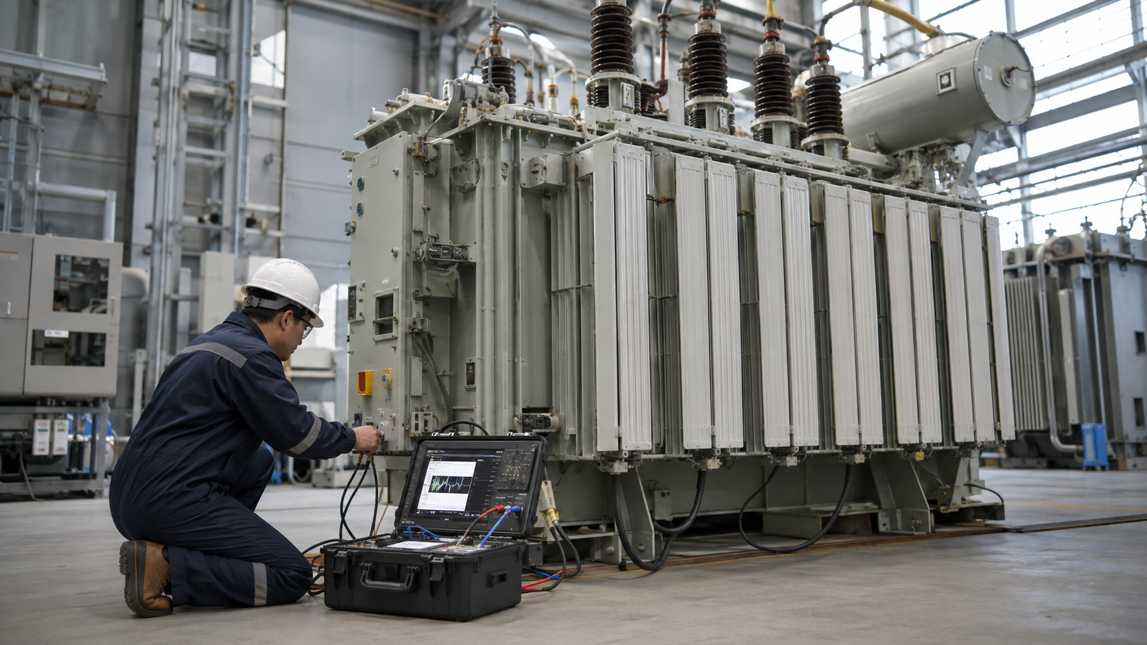
Transformer installation and maintenance determine whether a correctly designed unit reaches its expected service life. Industrial transformer replacement also requires more than matching kVA: voltage, impedance, vector group, dimensions, terminals, protection and outage sequence must align. This guide covers receiving, foundations, assembly, commissioning, condition maintenance and emergency replacement.
Scope: Industrial vs Small Appliance Transformers
Searches such as downlight, furnace, electric-fence or Better Homes and Gardens QuickFit transformer replacement refer to small appliance/control products. Those procedures do not apply to utility or industrial power transformers. High-energy equipment requires engineered isolation, lifting, grounding, testing and qualified personnel.
Pre-Installation Review
Approve the transformer datasheet and outline drawing before constructing foundations or cable interfaces. Verify kVA, HV/LV voltage, vector group, impedance, taps, insulation, cooling, oil volume, weight, center of gravity and accessories. Review transport route, lifting plan, clearances, fire separation, oil containment and grounding.
Quick Comparison and Selection Table
Use this table as a quick review of the main engineering and procurement decisions explained in the article.
| Decision area | Practical meaning | What to verify |
|---|---|---|
| Scope: Industrial vs Small Appliance Transformers | Searches such as downlight, furnace, electric-fence or Better Homes and Gardens QuickFit transformer replacement refer to small appliance/control products. | Those procedures do not apply to utility or industrial power transformers. |
| Pre-Installation Review | Approve the transformer datasheet and outline drawing before constructing foundations or cable interfaces. | Verify kVA, HV/LV voltage, vector group, impedance, taps, insulation, cooling, oil volume, weight, center of gravity and accessories. |
| Receiving Inspection | Check packaging, impact/tilt recorders, tank damage, leaks, pressure or nitrogen condition, oil level and accessory boxes. | Compare serial numbers and packing list. |
| Foundation and Site Preparation | Confirm concrete strength, level, anchors, rails and drainage. | The foundation must support operating and seismic loads. |
| Transformer Assembly | Large units may ship with radiators, conservator, bushings and coolers removed. | Follow approved lifting points and cleanliness controls. |
Receiving Inspection
Check packaging, impact/tilt recorders, tank damage, leaks, pressure or nitrogen condition, oil level and accessory boxes. Compare serial numbers and packing list. Inspect bushings and radiators and preserve moisture-sensitive items. Record photographs and nonconformities before accepting delivery.
Foundation and Site Preparation
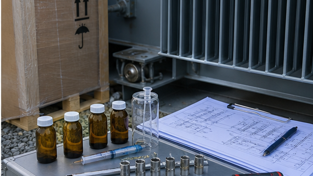
Confirm concrete strength, level, anchors, rails and drainage. The foundation must support operating and seismic loads. Provide radiator airflow, maintenance access, cable bending space and safe bushing clearances. Liquid units may require a bund, oil-water separation and fire wall.
Transformer Assembly
Large units may ship with radiators, conservator, bushings and coolers removed. Follow approved lifting points and cleanliness controls. Torque flanges, establish vacuum where required, fill/degas oil, leak-test and verify valve positions. Connect the designated core ground, tank earths and neutral grounding equipment.
Electrical Connections
Avoid transferring cable or bus mechanical force to bushings. Verify phase sequence, polarity, vector group, neutral and surge arresters. Apply approved connector materials and torque. CT secondary circuits require correct polarity and one designated grounding point.
Pre-Energization Tests
- Winding resistance and turns ratio/vector group.
- Insulation resistance and dielectric tests as specified.
- Oil quality and dissolved-gas baseline.
- Bushing and tap-changer checks.
- Cooling groups, temperature devices and alarms.
- CT polarity, relay injection and full trip-circuit tests.
- Grounding continuity and neutral equipment.
Initial Energization
Use an approved switching program. Confirm protection, DC supply, communications and emergency response. Energize no-load first where the plan requires, listen for abnormal sound and check voltage, phase rotation, current, leaks and temperature. Record baseline values for future comparison.
Preventive and Condition Maintenance
Inspection intervals depend on loading, environment, design and condition. Routine work includes visual leak/corrosion checks, oil level, cooling operation, temperature, breather, bushings, grounding, tap changer and terminal thermography. Keep vegetation, dust and animals controlled. For coordinating transformer work with switchgear, protection and station outages, use the substation maintenance planning guide.
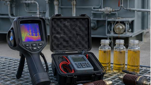
Dissolved-gas analysis trends thermal and electrical fault gases. Oil moisture, acidity and dielectric strength indicate fluid/insulation condition. Electrical tests may include winding resistance, ratio, power factor/tan delta, bushing capacitance, excitation and frequency-response analysis when justified. For online versus laboratory monitoring and trend interpretation, see our transformer DGA monitoring guide.
Transformer Fuse Replacement
A blown fuse is evidence, not a diagnosis. Determine whether overload, downstream fault, inrush coordination, insulation failure or a loose connection caused operation. Replace only with the approved voltage, current, class and interrupting rating after isolation and investigation. Never upsize a fuse simply to stop repeated operation. For fuse types and project-specific selection checks, see our transformer fuse guide.
Industrial Transformer Replacement Procedure
- Assess failure condition and whether repair is safe/economic.
- Confirm replacement electrical and physical compatibility.
- Perform load flow, fault and protection update where needed.
- Plan outage, temporary supply and switching boundaries.
- Prepare transport, lifting, oil handling and disposal.
- Isolate, test dead, ground and disconnect old equipment.
- Install, connect and test the replacement.
- Update settings, drawings, asset records and spares.
Replacement Time and Emergency Planning
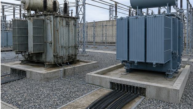
Replacement time depends on manufacturing lead time, transport permits, foundation changes, cable/bus modifications, oil processing, testing and utility approval. Emergency plans can include spare transformers, mobile units, standardized interfaces, preapproved transport routes and stored settings/drawings.
LBAJI Equipment Integration
A replacement 35 kV oil-immersed transformer can be specified around existing voltage and interface constraints. Packaged replacement may use a YBM-12 prefabricated substation or 35 kV new-energy box substation, subject to the system studies.
Transformer accessibility and transport requirements
Confirm transport dimensions, shipping mass, route restrictions, crane position, lifting attachments, foundation capacity and the future removal path. Indoor units also need ventilation and fire provisions. An installation can meet operating clearances yet be impossible to replace without major demolition.
Troubleshooting low secondary voltage
Low voltage can result from source variation, incorrect taps, overload, excessive conductor drop, loose connections, phase imbalance or an internal defect. Compare no-load and loaded voltages, current balance and tap position before changing settings. De-energize and test when abnormal sound, heat, odor or protection operation indicates a possible internal problem.
Technical references and further reading
The following independent sources support the standards, terminology, calculations, and safety context discussed in this guide:
- IEC 60076-1 power transformer standard — Scope, terminology, ratings, connection symbols, testing, safety, and general requirements for power transformers.
- U.S. Department of Energy: Distribution Transformers — Official definitions, efficiency requirements, test procedures, and regulatory resources for distribution transformers.
- OSHA electric power transmission and distribution requirements — Safety requirements relevant to construction and work around electric power transmission and distribution equipment.